155 Wyniki
Wyświetl wyniki:
Sortuj według:

W rozszerzeniu Projektowanie konstrukcji betonowych dla programu RFEM 6 można przeprowadzić obliczenia odporności ogniowej ścian i płyt żelbetowych zgodnie z uproszczoną metodą tabelaryczną (EN 1992-1-2, rozdział 5.4.2 oraz tabele 5.8 i 5.9).

Istnieje możliwość wymiarowania powierzchni z uwagi na warunki pożarowe przy użyciu metody zredukowanego przekroju. Redukcja jest stosowana na grubości powierzchni. Kontrolę obliczeń można przeprowadzić dla wszystkich materiałów drewnianych, które są dopuszczone dla obliczeń.
W przypadku drewna klejonego krzyżowo, w zależności od rodzaju kleju, można wybrać, czy możliwe jest odpadanie poszczególnych zwęglonych części warstwy, a tym samym, czy można spodziewać się zwiększonego zwęglenia w niektórych obszarach warstwy.

- 002691
- Ogólne informacje
- Projektowanie konstrukcji betonowych RFEM 6
- Projektowanie konstrukcji betonowych RSTAB 9
W rozszerzeniu Projektowanie konstrukcji betonowych można przeprowadzić uproszczone obliczenia odporności ogniowej słupów (Rozdział 5.3.2) i belek (Rozdział 5.6), zgodnie z EN 1992-1-2.
W przypadku uproszczonych obliczeń odporności ogniowej dostępne są następujące metody weryfikacji:
- Słupy: Minimalne wymiary przekroju prostokątnego i okrągłego wg tabeli 5.2a oraz równania 5.7 do obliczania czasu ekspozycji pożarowej
- Belki: Minimalne wymiary i odległości między środkami zgodnie z Tabelą 5.5 i Tabelą 5.6
Siły wewnętrzne do obliczeń odporności ogniowej można wyznaczyć przy użyciu dwóch metod.
- 1: W tym przypadku siły wewnętrzne z wyjątkowej sytuacji obliczeniowej są bezpośrednio uwzględniane w obliczeniach.
- 2: Siły wewnętrzne z obliczeń w temperaturze normalnej są redukowane za pomocą współczynnika Eta,fi (ηfi) i są następnie wykorzystywane do obliczeń odporności ogniowej.
Ponadto istnieje możliwość modyfikacji rozstawu osi zgodnie z równ. 5.5.

Rozszerzenie Projektowanie konstrukcji betonowych umożliwia wymiarowanie prętów i powierzchni ze względu na zmęczenie zgodnie z EN 1992-1-1, rozdział 6.8.
W przypadku obliczeń zmęczenia można opcjonalnie wybrać dwie metody lub poziomy obliczeniowe w konfiguracjach obliczeniowych:
- Poziom obliczeniowy 1: Obliczenia uproszczone wg. do 6.8.6 i 6.8.7(2) Kryterium uproszczone jest stosowane dla częstych kombinacji oddziaływań zgodnie z EN 1992-1-1, rozdział 6.8.6 (2) oraz EN 1990, równ. (6.15b) wraz z obciążeniami od ruchu drogowego w stanie użytkowalności. Dla stali zbrojeniowej sprawdzany jest maksymalny zakres naprężeń zgodnie z 6.8.6. Naprężenie ściskające w betonie jest określane za pomocą górnego i dolnego dopuszczalnego naprężenia zgodnie z 6.8.7(2).
- Poziom analizy 2: Obliczanie równoważnego naprężenia niszczącego zgodnie z 6.8.5 i 6.8.7(1) (uproszczone obliczenia na zmęczenie): Obliczenia z wykorzystaniem zakresów równoważnych naprężeń niszczących są przeprowadzane dla kombinacji zmęczeniowych, zgodnie z EN 1992-1-1, rozdział 6.8.3, równ. (6.69) o specyficznie zdefiniowanym oddziaływaniu cyklicznym Qfat .

W rozszerzeniu Projektowanie konstrukcji betonowych można przeprowadzać obliczenia sejsmiczne dla prętów żelbetowych zgodnie z EC 8. Są to między innymi następujące funkcje:
- Konfiguracje obliczeń sejsmicznych
- Rozróżnianie klas ciągliwości DCL, DCM, DCH
- Możliwość przeniesienia współczynnika odpowiedzi z analizy dynamicznej
- Sprawdzenie wartości granicznej współczynnika odpowiedzi
- Weryfikacja nośności dla "Wytrzymały słup - słaba belka"
- Uszczegółowienie i reguły szczególne dla współczynnika ciągliwości krzywizny
- Uszczegółowienie i reguły szczególne dla ciągliwości lokalnej

Teraz w rozszerzeniu Projektowanie konstrukcji betonowych można wymiarować elementy wykonane z betonu zbrojonego włóknami zgodnie z wytyczną "DAfStb Steel Fiber-Reinforced Concrete".
Ta opcja jest dostępna dla obliczeń zgodnie z EN 1992-1-1. Obliczenia zgodnie z wytyczną DAfStb są przeprowadzane po przypisaniu betonu typu "Fibrobeton" do elementu konstrukcyjnego z betonu zbrojonego.
Przejdź do filmu
W zakładce "Zbrojenie na ścinanie" można wybrać opcję "Powiązania krzyżowe na wolnych prętach zbrojeniowych z aktywnym wyborem w oknie graficznym". Pozwala to na umieszczenie dodatkowych powiązań krzyżowych na wolnych prętach zbrojenia podłużnego.
Pozycję więzów krzyżowych można aktywować lub dezaktywować w infografice. Powiązania krzyżowe są uwzględniane podczas kontroli stanu granicznego nośności i obliczeń konstrukcji. Są one dostępne dla obliczeń zgodnie z EN 1992-1-1.
Przejdź do filmu
Czy wiecie, że...? W podporach obliczeniowych można teraz zdefiniować śruby z pełnym gwintem jako poprzeczne elementy wzmacniające ściskanie dla obliczenia "Ściskania w poprzek włókien". Śruby są sprawdzane pod kątem wciśnięcia i wyboczenia.
Dodatkowo sprawdzana jest nośność na ścinanie w płaszczyźnie wierzchołka śruby. Kąt rozłożenia obciążenia można uwzględnić liniowo poniżej 45° lub nieliniowo (zgodnie z Bejtka, I. (2005). Verstärkung von Bauteilen aus holz mit vollgewindeschrauben. KIT Scientific Publishing.

W programach RFEM i RSTAB można wymiarować pręty przy użyciu materiału typu "Fornir klejony warstwowo". Dostępni są następujący producenci:
- Pollmeier (Baubuche)
- Metsä (kerto LVL)
- STEICO
- Stora Enso
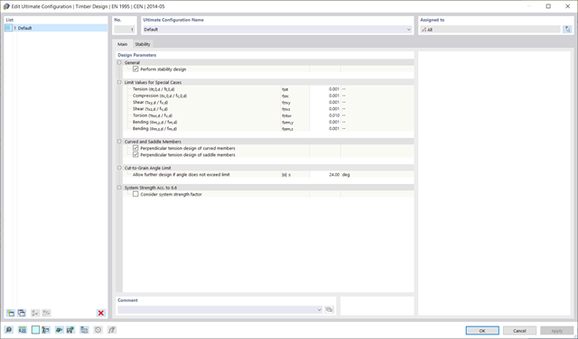
W konfiguracji stanu granicznego nośności można uwzględnić współczynniki wytrzymałości w celu zwiększenia wytrzymałości. Niezależnie od tego współczynniki zmniejszające wytrzymałości są uwzględniane automatycznie. Wypróbuj teraz!
Przejdź do filmu
Rozszerzenie Projektowanie konstrukcji drewnianych dla RFEM umożliwia wymiarowanie prętów i powierzchni zgodnie z Eurokodem 5, SIA 265 (norma szwajcarska), CSA O86 (norma kanadyjska) lub ANSI/AWC NDS (norma amerykańska), np. drewno klejone krzyżowo, drewno klejone warstwowo, drewno iglaste, materiały drewnopochodne itp.
Przejdź do filmu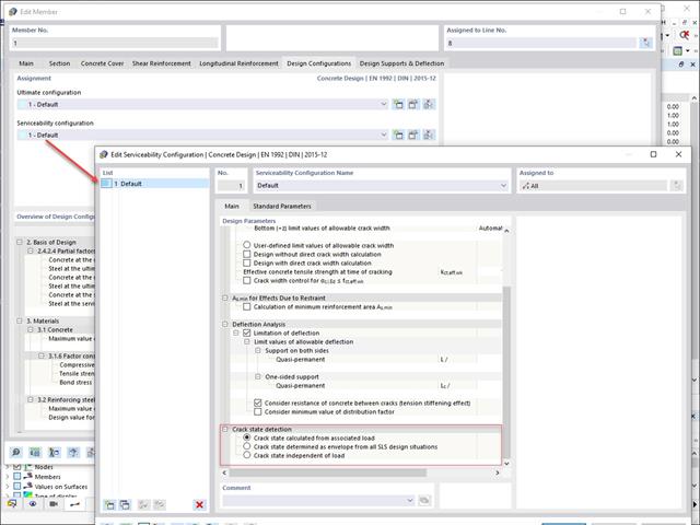
W konfiguracji stanu granicznego użytkowalności można dostosowywać różne parametry obliczeniowe przekrojów. W tym miejscu można kontrolować warunek przekroju zastosowany do analizy odkształcenia i szerokości zarysowania.
Można aktywować następujące ustawienia:
- Stan zarysowania obliczony na podstawie powiązanego obciążenia
- Stan zarysowany obliczony jako obwiednia ze wszystkich sytuacji obliczeniowych SGU
- Stan przekroju zarysowanego - niezależny od obciążenia

- 002133
- Ogólne informacje
- Projektowanie konstrukcji drewnianych RFEM 6
- Projektowanie konstrukcji drewnianych RSTAB 9
- Szeroki wybór przekrojów, takich jak przekroje prostokątne, kwadratowe, teowe, okrągłe, złożone, nieregularne przekroje parametryczne i wiele innych (przydatność do obliczeń zależy od wybranej normy)
- Wymiarowanie drewna klejonego krzyżowo (CLT)
- Wymiarowanie materiałów drewnopochodnych i drewna klejonego warstwowo zgodnie z EC 5
- Wymiarowanie prętów o zmiennym przekroju (metoda zgodna z normą)
- Możliwe jest dostosowanie istotnych współczynników obliczeniowych i parametrów normowych
- Elastyczność dzięki szczegółowym opcjom ustawień dla podstawy i zakresu obliczeń
- Szybkie i przejrzyste wyświetlanie wyników dla globalnej oceny ich rozkładu na konstrukcji po zakończeniu obliczeń
- Szczegółowe wyniki obliczeń i niezbędne wzory (jasna i łatwa do zweryfikowania ścieżka wyników)
- Przejrzyste zestawienie wyników w formie numerycznej w stosownych oknach oraz możliwość ich graficznego przedstawienia na konstrukcji
- Integracja wyników z protokołem wydruku programu RFEM/RSTAB
- 002134
- Ogólne informacje
- Projektowanie konstrukcji drewnianych RFEM 6
- Projektowanie konstrukcji drewnianych RSTAB 9
- Wymiarowanie elementów rozciąganych, ściskanych, zginanych, ścinanych, skręcanych i poddanych połączonemu działaniu tych sił wewnętrznych
- Uwzględnienie podcięcia
- Obliczanie ściskania prostopadle do włókien na podporach końcowych i pośrednich z (EC 5) i bez elementów wzmacniających (śruby z pełnym gwintem)
- Opcjonalna redukcja siły tnącej na podporze
- Wymiarowanie prętów zakrzywionych i zbieżnych
- Uwzględnianie wyższych wytrzymałości dla podobnych elementów, które znajdują się blisko siebie (współczynnik ksys wg EN 1995-1-1, 6.6(1)-(3))
- Możliwość zwiększenia nośności na ścinanie dla drewna iglastego zgodnie z DIN EN 1995‑1‑1:NA NDP do 6.1.7(2)
- 002135
- Obliczenia
- Projektowanie konstrukcji drewnianych RFEM 6
- Projektowanie konstrukcji drewnianych RSTAB 9
- Analiza stateczności dla wyboczenia giętnego, wyboczenia skrętnego i wyboczenia giętno-skrętnego przy ściskaniu
- Import długości efektywnych z obliczeń przy użyciu rozszerzenia Stateczność konstrukcji
- Graficzne wprowadzanie i kontrola zdefiniowanych podpór węzłowych oraz długości efektywnych w celu analizy stateczności
- Określanie długości zastępczych prętów o zbieżnym przekroju
- Uwzględnienie położenia stężenia zwichrzenia
- Analiza zwichrzenia elementów poddanych obciążeniu momentem
- W zależności od normy istnieje wybór między wprowadzaniem wartości Mcr przez użytkownika, metodą analityczną z normy lub wykorzystaniem wewnętrznego solwera wartości własnych
- Uwzględnienie panelu usztywniającego i ograniczenia obrotu podczas korzystania z solwera wartości własnych
- Graficzne przedstawienie postaci własnej w przypadku zastosowania solwera wartości własnych
- Analiza stateczności elementów konstrukcyjnych ze ściskaniem i naprężeniem zginającym, w zależności od normy obliczeniowej
- Przejrzyste obliczenia wszystkich niezbędnych współczynników, takich jak współczynniki uwzględniające rozkładu momentów lub współczynniki interakcji
- Alternatywne uwzględnienie wszystkich wpływów dla analizy stateczności podczas określania sił wewnętrznych w programie RFEM/RSTAB (analiza drugiego rzędu, imperfekcje, redukcja sztywności, ewentualnie w połączeniu z rozszerzeniem Skręcanie skrępowane (7 stopni swobody))

- 002372
- Ogólne informacje
- Projektowanie konstrukcji drewnianych RFEM 6
- Projektowanie konstrukcji drewnianych RSTAB 9
- Dowolna definicja czasu zwęglania
- W przypadku konstrukcji powierzchniowych (drewno klejone krzyżowo) można obliczyć z przyczepnością lub bez
- Bezpłatna, zdefiniowana przez użytkownika specyfikacja parametrów pożaru
- Uwzględnienie różnych długości efektywnych do obliczania odporności ogniowej
- Opcjonalne obliczenia dla 'ściskania w poprzek włókien'
- Zintegrowane z RFEM/RSTAB graficzne wyświetlanie wyników, np. B. Stopień wykorzystania
- Pełna integracja wyników z protokołem wydruku programu RFEM/RSTAB
- 002373
- Ogólne informacje
- Projektowanie konstrukcji drewnianych RFEM 6
- Projektowanie konstrukcji drewnianych RSTAB 9
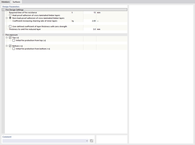
Program RFEM/RSTAB oferuje również szereg funkcji na wypadek pożaru. Program umożliwia automatyczne generowanie kombinacji obciążeń i wyników dla wyjątkowej sytuacji obliczeniowej w obliczeniach odporności ogniowej. Pręty, które mają zostać zwymiarowane wraz z odpowiednimi siłami wewnętrznymi, są importowane bezpośrednio z programu RFEM/RSTAB. Przechowywane są również wszystkie informacje o materiale i przekroju. Nie musisz'robić nic więcej.
Parametry istotne dla obliczeń odporności ogniowej można definiować poprzez przypisanie konfiguracji odporności ogniowej do obliczanych prętów i powierzchni. Ponadto można wprowadzić dalsze szczegółowe ustawienia, takie jak zdefiniowanie ekspozycji na ogień z jednej strony aż po wszystkie strony.
- 002374
- Ogólne informacje
- Projektowanie konstrukcji drewnianych RFEM 6
- Projektowanie konstrukcji drewnianych RSTAB 9
Jak zapewne wiesz, weryfikacje są przeprowadzane dla wybranych prętów z uwzględnieniem zdefiniowanego czasu zwęglania. Wszystkie niezbędne współczynniki i współczynniki redukcyjne są zapisywane w programie i uwzględniane przy określaniu nośności konstrukcji. Pozwala to zaoszczędzić dużo pracy.
Długości efektywne dla obliczeń pręta zastępczego są pobierane bezpośrednio z danych dotyczących wytrzymałości. Nie trzeba ich ponownie wprowadzać.
Po zakończeniu obliczeń program wyświetla w przejrzysty sposób obliczenia odporności ogniowej ze wszystkimi szczegółami wyników. Pozwala to na przejrzyste śledzenie wyników. Wyniki zawierają również wszystkie wymagane parametry, dzięki czemu można określić temperaturę elementu w czasie projektowania.
Oprócz wszystkich tych funkcji, program umożliwia zintegrowanie wszystkich tabel wyników i grafik, w tym wyników stanu granicznego nośności i użytkowalności, z globalnym protokołem wydruku programu RFEM/RSTAB, jako część wyników obliczeń stali.
- 002375
- Ogólne informacje
- Projektowanie konstrukcji drewnianych RFEM 6
- Projektowanie konstrukcji drewnianych RSTAB 9
W przypadku obliczeń zgodnie z Eurokodem 5 parametry załączników krajowych (NA) są zintegrowane dla następujących krajów:
-
 DIN EN 1995-1-1/NA:2014-07 (Niemcy)
 -
 ÖNORM EN 1995-1-1/NA:2019-06 (Austria)
 -
 SN EN 1995-1-1/NA:2015-03 (Szwajcaria)
 -
 BDS EN 1995-1-1/NA:20157-06 (Bułgaria)
 -
 BS EN 1995-1-1/NA:2019-09 (Wielka Brytania)
 -
 CEN EN 1995-1-1/2014-05 (Unia Europejska)
 -
 CYS EN 1995-1-1/NA:2019-06 (Cypr)
 -
 CZE EN 1995-1-1/NA:2015-05 (Republika Czeska)
 -
 DS EN 1995-1-1/NA:2019-09 (Dania)
 -
 ELOT EN 1995-1-1/NA:2010-01 (Grecja)
 -
 EVS EN 1995-1-1/NA:2015-11 (Estonia)
 -
 HRN EN 1995-1-1/NA:2015-03 (Chorwacja)
 -
 I S. EN 1995-1-1/NA:2014-05 (Irlandia)
 -
 ILNAS EN 1995-1-1/NA:2020-3 (Luksemburg)
 -
 IST EN 1995-1-1/NA:2014-09 (Islandia)
 -
 LST EN 1995-1-1/NA:2014-06 (Litwa)
 -
 LVS EN 1995-1-1/NA:2014-12 (Łotwa)
 -
 MSZ EN 1995-1-1/NA:2015-06 (Węgry)
 -
 NBN EN 1995-1-1/NA:2014-06 (Belgia)
 -
 NEN EN 1995-1-1/NA:2014-06 (Holandia)
 -
 NF EN 1995-1-1/NA:2020-04 (Francja)
 -
 NP EN 1995-1-1/NA:2014-09 (Portugalia)
 -
 NS EN 1995-1-1/NA:2014-08 (Norwegia)
 -
 PN EN 1995-1-1/NA:2014-07 (Polska)
 -
 SFS EN 1995-1-1/NA:2016-12 (Finlandia)
 -
 SIST EN 1995-1-1/NA:2018-01 (Słowenia)
 -
 SR EN 1995-1-1/NA:2014-12 (Rumunia)
 -
 SS EN 1995-1-1/NA:2018-02 (Singapur)
 -
 SS EN 1995-1-1/NA:2014-05 (Szwecja)
 -
 STN EN 1995-1-1/NA:2019-12 (Słowacja)
 -
 TKP EN 1995-1-1/NA:2019-09 (Białoruś)
 -
 UNE EN 1995-1-1/NA:2016-04 (Hiszpania)
 -
 UNI EN 1995-1-1/NA:2016-11 (Włochy)

- 002377
- Ogólne informacje
- Projektowanie konstrukcji drewnianych RFEM 6
- Projektowanie konstrukcji drewnianych RSTAB 9
Masz wiele możliwości w projektowaniu konstrukcji drewnianych. Dla prętów o zmiennym przekroju i zakrzywionych, możliwe jest uwzględnienie kątów nacięcia względem włókien, naprężeń rozciągających poprzecznych oraz zależnych od objętości promieni krzywizny. Aby obliczyć pole przekroju włókien, wytrzymałość na rozciąganie lub zginanie jest odpowiednio dostosowywana. Aby umożliwić również przeprowadzenie analizy stateczności metodą prętów zastępczych, wysokość do wyznaczenia długości efektywnej i długości wyboczeniowej została ustawiona jako odległość 0,65 × h od rzeczywistego punktu obliczeniowego.
- 002378
- Ogólne informacje
- Projektowanie konstrukcji drewnianych RFEM 6
- Projektowanie konstrukcji drewnianych RSTAB 9
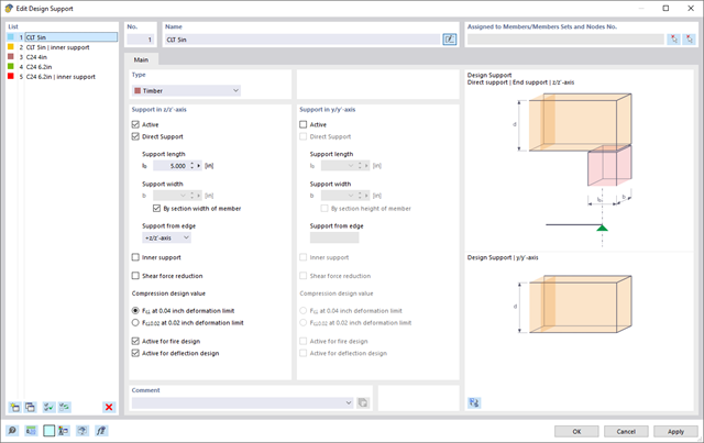
Tutaj masz wolny wybór. Obliczenie ciśnienia w podporach można przeprowadzić w dowolnym punkcie dla obciążenia w kierunkach y i z przekroju. Użytkownik może dowolnie rozróżnić podpory wewnętrzne i zewnętrzne. Użytkownik może zdefiniować współczynnik kc,90 dla parcia prostopadłego do włókien (np. 1,75 dla drewna klejonego warstwowo). Jeżeli jest to dozwolone, długość podpory jest automatycznie zwiększana zgodnie ze specyfikacjami normy. Dzięki temu można przeprowadzić bardziej efektywne obliczenia przy minimalnym wysiłku.
- 002379
- Ogólne informacje
- Projektowanie konstrukcji drewnianych RFEM 6
- Projektowanie konstrukcji drewnianych RSTAB 9
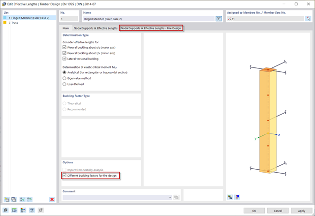
Dla podpór bocznych konstrukcji często nie są przeprowadzane obliczenia odporności ogniowej. Chcesz rozwiązać ten problem w swoim projekcie? Aby uwzględnić ten fakt w obliczeniach, można zdefiniować inne długości prętów zastępczych dla sytuacji pożarowej.
- 002380
- Ogólne informacje
- Projektowanie konstrukcji drewnianych RFEM 6
- Projektowanie konstrukcji drewnianych RSTAB 9
Co się dzieje, gdy jest z wiatrem? Stężenie giętno-skrętne nie jest stosowane w celu zredukowania długości efektywnych i długości zwichrzenia.
- 002381
- Ogólne informacje
- Projektowanie konstrukcji drewnianych RFEM 6
- Projektowanie konstrukcji drewnianych RSTAB 9
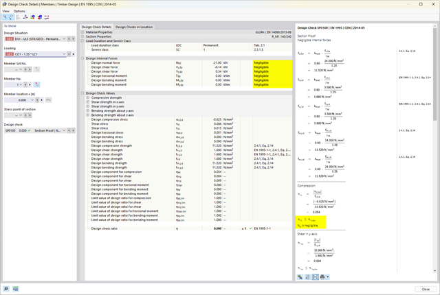
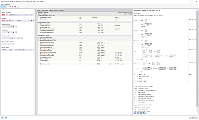
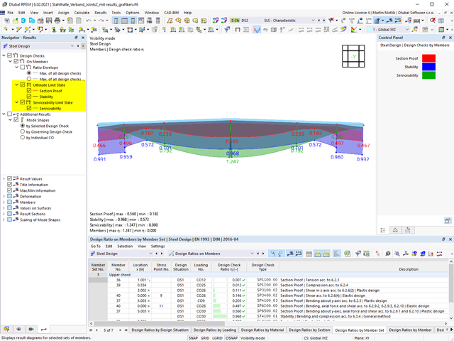
Dzięki oprogramowaniu Dlubal wszystko jest łatwiejsze. Przeprowadzone obliczenia normy projektowej są przedstawione w przejrzysty sposób. Dla każdego warunku projektowego określane jest kryterium obliczeniowe. Ponadto program dostarcza szczegółowe informacje na temat obliczeń, w tym wartości początkowe, wyniki pośrednie i wyniki końcowe. Proces obliczeń wraz z zastosowanymi wzorami, standardowymi źródłami i wynikami szczegółowo przedstawiony jest w oknie informacyjnym w szczegółach obliczeń.
- 002382
- Ogólne informacje
- Projektowanie konstrukcji drewnianych RFEM 6
- Projektowanie konstrukcji drewnianych RSTAB 9
Nadal szukasz projektu? Kontrole obliczeń są dostępne w formie tabelarycznej w rozszerzeniu Projektowanie konstrukcji drewnianych. Program może również przedstawić rozkład stopni wykorzystania w sposób graficzny. W tabeli oraz w wynikach graficznych dostępne są obszerne opcje filtrowania, umożliwiające wyświetlanie żądanych warunków projektowych według stanu granicznego lub typu obliczeniowego.

- 002383
- Ogólne informacje
- Projektowanie konstrukcji drewnianych RFEM 6
- Projektowanie konstrukcji drewnianych RSTAB 9
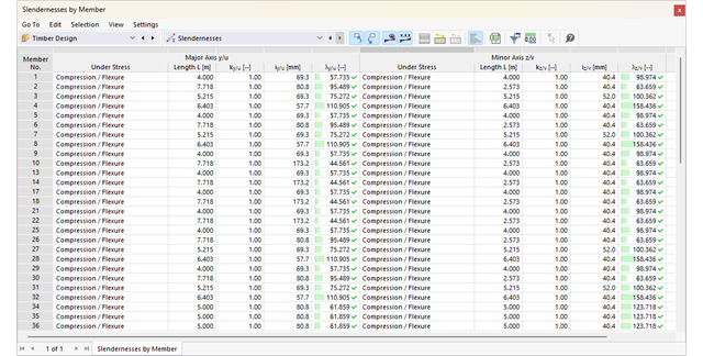
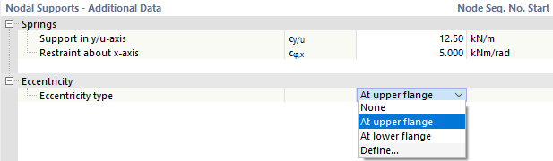
Masz pytania dotyczące programu? W zależności od kierunku można indywidualnie zdefiniować długości odniesienia, które zostaną uwzględnione podczas obliczeń wartości granicznej ugięcia oraz które segmenty mają zostać sprawdzone. W tym celu należy zdefiniować podpory obliczeniowe w węzłach pośrednich pręta i przydzielić je do odpowiedniego kierunku na potrzeby analizy odkształceń. W segmentach wynikowych można również zdefiniować wygięcie wstępne dla każdego kierunku i segmentu.
- 002384
- Ogólne informacje
- Projektowanie konstrukcji drewnianych RFEM 6
- Projektowanie konstrukcji drewnianych RSTAB 9
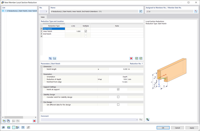
Redukcja przekroju pręta umożliwia uwzględnienie podcięcia początkowego, wewnętrznego lub końcowego belki. Redukcja belki jest zatem uwzględniana w obliczeniach nośności. Nie dotyczy to jednak sztywności.
- 002385
- Ogólne informacje
- Projektowanie konstrukcji drewnianych RFEM 6
- Projektowanie konstrukcji drewnianych RSTAB 9
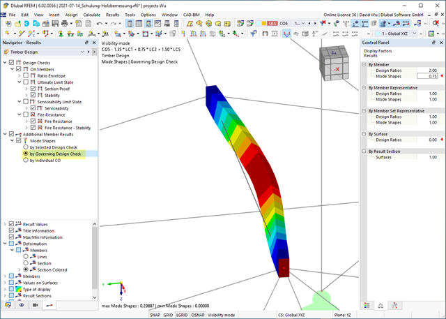
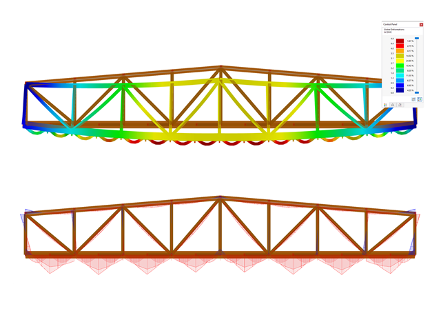
Czy do określenia współczynnika obciążenia krytycznego w ramach analizy stateczności użyto solwera wartości własnych rozszerzenia? W takim przypadku można wyświetlić decydujący kształt drgań własnych projektowanego obiektu. W tym miejscu dostępny jest solwer wartości własnych do analizy zwichrzenia, w zależności od zastosowanej normy obliczeniowej.
- 002386
- Obliczenia
- Projektowanie konstrukcji drewnianych RFEM 6
- Projektowanie konstrukcji drewnianych RSTAB 9
Układ konstrukcyjny można wprowadzić i obliczyć siły wewnętrzne w programach RFEM i RSTAB. Użytkownik ma pełny dostęp do obszernych bibliotek materiałów i przekrojów.
Projektowanie konstrukcji drewnianych jest w pełni zintegrowane z programami głównymi. Jednocześnie automatycznie uwzględnia konstrukcję i dostępne wyniki obliczeń. Do wymiarowanych obiektów można przydzielić dodatkowe dane dla wymiarowania drewna, takie jak długości efektywne, redukcje przekroju lub parametry obliczeniowe. Elementy można wybrać graficznie w wielu miejscach programu za pomocą funkcji [Wybrać].
- 002387
- Obliczenia
- Projektowanie konstrukcji drewnianych RFEM 6
- Projektowanie konstrukcji drewnianych RSTAB 9
Jeśli projekt się powiedzie, nadejdzie czas. Ponieważ program wykonuje za Ciebie wiele procesów. Przeprowadzone kontrole obliczeń są na przykład wyświetlane w tabeli. Tutaj wyświetlane są wszystkie szczegóły wyników. Dzięki przejrzyście przedstawionym wzorom obliczeniowym wyniki są bezproblemowe i zrozumiałe. Nie ma tu efektu "czarnej skrzynki".
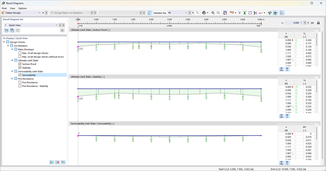
Obliczenia są przeprowadzane we wszystkich decydujących miejscach prętów i przedstawiane graficznie w postaci wykresu wyników. Ponadto w wynikach dostępne są szczegółowe grafiki, takie jak rozkład naprężeń w przekroju lub decydujący kształt postaci drgań.
Wszystkie dane wejściowe i wyniki są częścią protokołu wydruku programu RFEM/RSTAB. Zawartość protokołu i jego zakres można wybrać specjalnie dla poszczególnych warunków projektowych.
- 002369
- Ogólne informacje
- Projektowanie konstrukcji drewnianych RFEM 6
- Projektowanie konstrukcji drewnianych RSTAB 9
- Obliczanie ugięć i porównanie z normatywnymi lub ręcznie dostosowanymi wartościami granicznymi
- Uwzględnienie wygięcia wstępnego w analizie ugięcia
- W zależności od typu sytuacji obliczeniowej możliwe są różne wartości graniczne
- Ręczne dostosowywanie długości odniesienia i segmentacji według kierunku
- Obliczanie ugięć w odniesieniu do konstrukcji początkowej lub do konstrukcji odkształconej
- Automatyczne uwzględnienie odkształceń zależnych od czasu poprzez zwiększenie obciążenia o współczynnik pełzania (może być również zdefiniowany przez użytkownika po stronie sztywności)
- Uproszczone obliczenia drgań
- Graficzne wyświetlanie wyników zintegrowane z RFEM/RSTAB; na przykład stopień wykorzystania wartości granicznej, odkształcenie lub ugięcie
- Pełna integracja wyników z protokołem wydruku programu RFEM/RSTAB