


The single-story Visitors' Centre includes a café and features a mass timber and light wood frame. From there, an accessible 650 m (2,132 ft) long treetop walk leads visitors onto a spectacular gentle spiral ramp up 30 m (98 ft) to a lookout with stunning views of Finlayson Arm and the distant Coast Mountains.
Structure
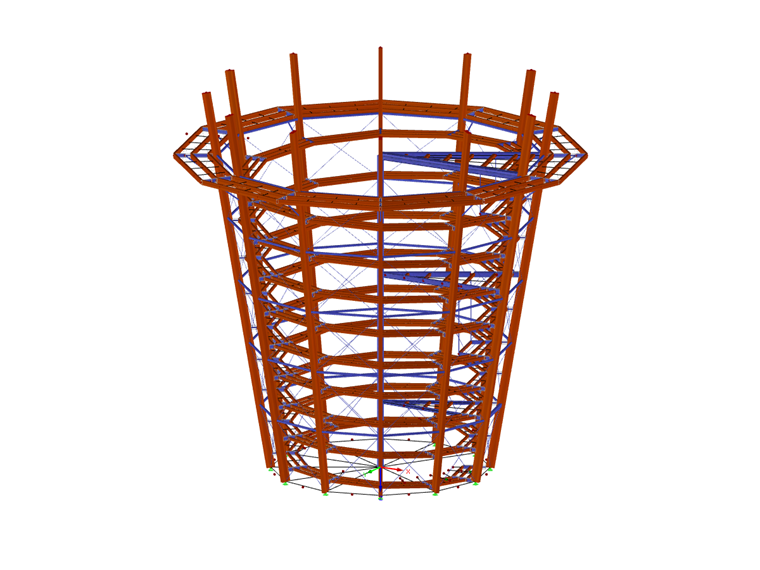
The primary structural system consists of glulam columns with steel X-bracing around the perimeter. Outriggers from these columns create a spiral walkway with a length of 600 m (1,967 ft), transporting visitors to the top of the structure and giving access to the viewing platform. A galvanized steel central spiral staircase provides emergency egress.
This project aims to protect and enhance the ecological values of the park, collaborate with First Nations, balance public use with ecological values, and connect visitors with the park’s natural values and cultural heritage.
| Location | 901 Trans-Canada Hwy Malahat BC V0R 2L0 Canada |
| Investor | Malahat Skywalk Corp. malahatskywalk.com |
| Structural Analysis | Aspect Structural Engineers aspectengineers.com |
| Architecture | Muroch & Company Architecture & Planning |
| Design and Construction | Kinsol Timber Systems
Kinsol Timber Systems www.kinsoltimber.com |
| 3D Detailing & Shop Drawings | Styxworks styxworks.com |


