Both RFEM and RSTAB have an interface for exporting models to RWIND where the wind (in terms of speed and turbulence) can be defined in tabular form or, even more practically, on the basis of a wind standard specification.
When running the RWIND program manually, no interface in RFEM or RSTAB is required and you can define the height-dependent wind load and other fluid-mechanical data directly in RWIND. In addition, you can directly model the structures and the terrain environment by importing VTP, STL, OBJ, and IFC files.
This article will demonstrate wind load generation in RWIND 2 as a complement to RFEM 6 for complete structural analysis and design.
Practical Example
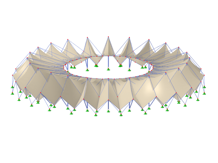
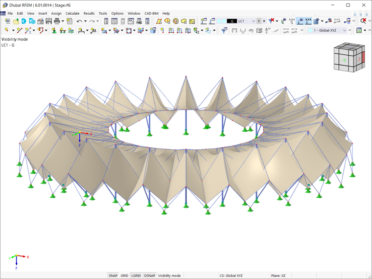
The structure used in this example is a stadium roof consisting of membranes, as shown in Image 1. Given that the structure has already been modeled in RFEM 6 and load cases for the permanent, prestress, and imposed loads have been defined, a separate load case for the application of wind load should be created.
It is important to highlight that if form-finding is considered, the associated shape must be taken as an initial state in the wind analysis. By doing so, you avoid incorrect surface geometries in the wind tunnel.
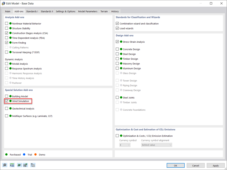
First, it is important to make sure that Wind Simulation as a special solution add-on is activated in the Base Data of the model (Image 2). This will allow you to select Wind Simulation as an analysis type for the wind load case, as in Image 3.
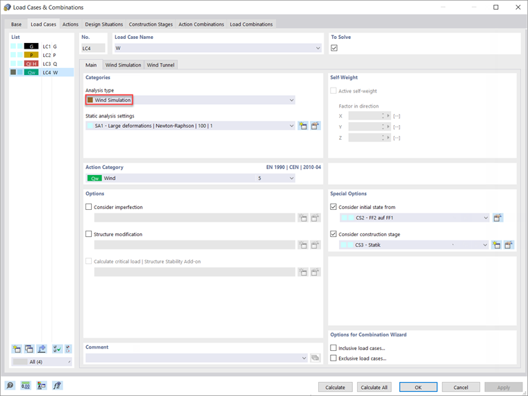
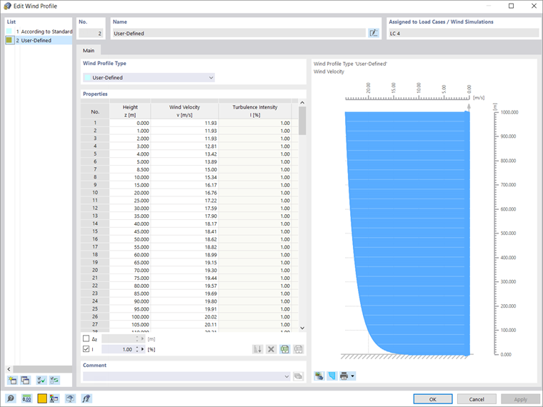
Two new registers are now available. In Wind Simulation (Image 4), you can use the model for wind simulation in a numerical wind tunnel where the wind medium is defined on the basis of the wind simulation analysis settings, the wind direction around the Z-axis (clockwise), the terrain offset, and the wind profile itself. As a matter of fact, you can use a wind profile according to the preferred standard, or you can define it yourself, as in Image 5.
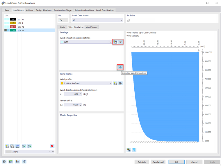
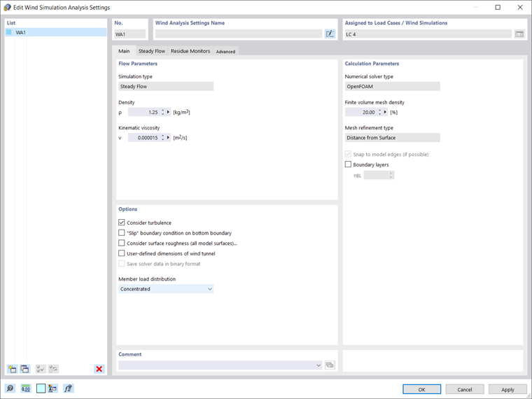
To define the wind simulation analysis settings, you can select the “Create new wind simulation settings” icon as indicated in Image 4 and insert flow parameters, calculation parameters, and other options (Image 6).
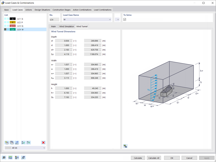
The dimensions of the wind tunnel are automatically defined according to the selected standard. They are displayed in the Wind Tunnel tab, as shown in Image 7.
Given that you have defined the input data in terms of wind simulation settings and wind tunnel, you can now start to calculate the wind load. This is a two-step process that is discussed in the following paragraph.
First, in the background, a batch process starts that places the model in the numerical wind tunnel of RWIND. Next, a CFD analysis is initiated and once the simulation is finished, the resulting surface pressures for a selected time step are returned into the respective load cases of RFEM or RSTAB as FE mesh nodal loads or member loads.
You can also initialize the wind simulation alone using the “Calculate Wind Simulation” icon shown in Image 4.
Calculation and Results
As previously mentioned, RWIND uses a numerical CFD model to simulate wind flows around objects using a digital wind tunnel. The simulation process is based on 3D volume mesh and it determines specific wind loads on the model surfaces from the flow result around the model.
You can calculate the wind flows by using the basic (RWIND Basic) or the pro (RWIND Pro) program package. The former provides a stationary solver, whereas the latter provides both the stationary and the transient solver. The basic program package employs the turbulence models RAS k-ω and RAS k-ε, whereas the LES SpalartAllmarasDDES turbulence model is a feature of the pro (RWIND Pro) program package.
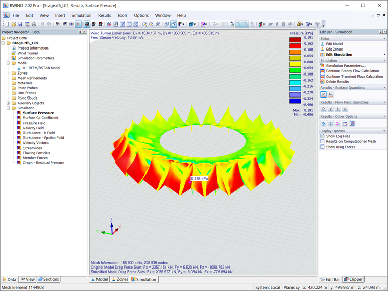
Hence, the program is simulating the wind flow by determining the pressure field, velocity field, and turbulence field around the structure geometry, as well as the velocity vectors and streamlines around the structure geometry. The surface pressure and the surface Cp coefficients are also calculated (Image 8).
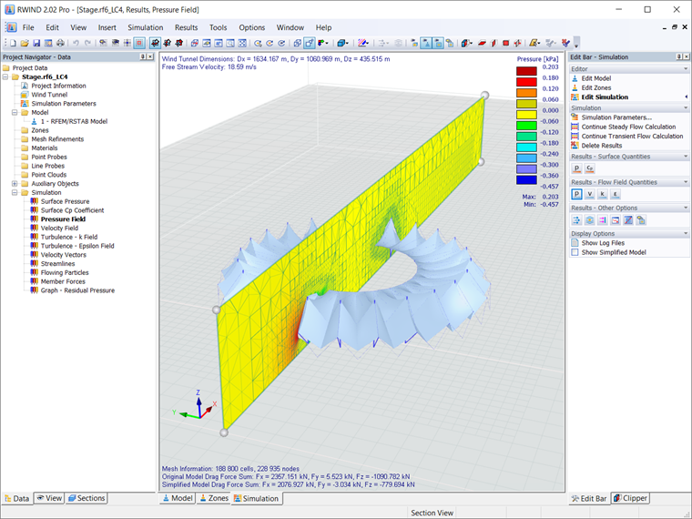
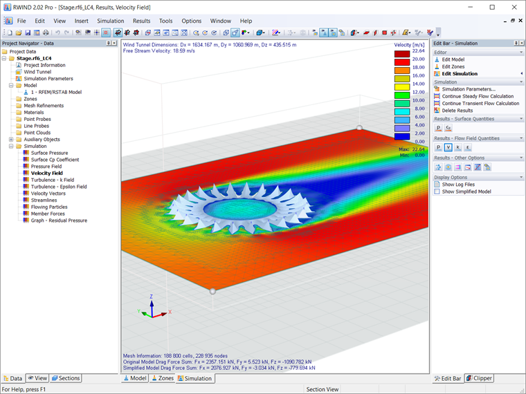
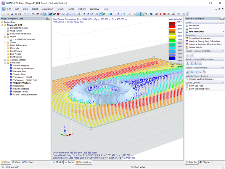
You can display the above-mentioned results for freely definable zones graphically (as both images and videos). For better evaluation, RWIND provides freely movable slicer planes for the separate display of the "solid results" in a plane (Images 9, 10, and 11).
Animated display in the form of moving line segments or particles for the 3D branched streamline result is also possible, thus allowing for representation of the wind flow as a dynamic effect. Furthermore, you can export the results as an image or a video (especially for animated results).
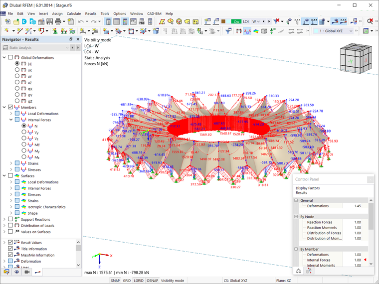
Once the CFD analysis is performed, the resulting surface pressures for a selected time step are automatically transferred into the respective load cases of RFEM (or RSTAB) as FE mesh nodal loads or member loads. Hence, the calculation of these load cases is carried out and it results in internal forces, deformations, stresses, and so forth, as shown in Image 12.
In this manner, the load cases that contain the wind load distribution generated with RWIND can be combined with other loads into load and result combinations, and can be used for further analysis and design.