107 Results
View Results:
Sort by:

Using the Timber Design add-on, timber column design is possible according to the 2018 NDS standard ASD method. Accurately calculating timber member compressive capacity and adjustment factors is important for safety considerations and design. The following article will verify the maximum critical buckling strength calculated by the Timber Design add-on using step-by-step analytical equations as per the NDS 2018 standard including the compressive adjustment factors, adjusted compressive design value, and final design ratio.

Wind direction plays a crucial role in shaping the outcomes of Computational Fluid Dynamics (CFD) simulations and the structural design of buildings and infrastructures. It is a determining factor in assessing how wind forces interact with structures, influencing the distribution of wind pressures, and consequently, the structural responses. Understanding the impact of wind direction is essential for developing designs that can withstand varying wind forces, ensuring the safety and durability of structures. Simplified, the wind direction helps in fine-tuning CFD simulations and guiding structural design principles for optimal performance and resilience against wind-induced effects.

The Geotechnical Analysis add-on provides RFEM with additional specific soil material models that are able to suitably represent complex soil material behavior. This technical article is an introduction to show how the stress-dependent stiffness of soil material models can be determined.

Compliance with building codes, such as Eurocode, is essential to ensure the safety, structural integrity, and sustainability of buildings and structures. Computational Fluid Dynamics (CFD) plays a vital role in this process by simulating fluid behavior, optimizing designs, and helping architects and engineers meet Eurocode requirements related to wind load analysis, natural ventilation, fire safety, and energy efficiency. By integrating CFD into the design process, professionals can create safer, more efficient, and compliant buildings that meet the highest standards of construction and design in Europe.

The events of recent years remind us of the importance of earthquake engineering in seismic regions. For you as an engineer, the design of structures in earthquake-prone areas is a constant trade-off between economic efficiency – the financial possibilities – and structural safety. If a collapse is inevitable, engineers must estimate how it will affect the structure. This article aims to provide you with an option on how to perform this estimation.

The modal relevance factor is a result of the linear stability analysis and qualitatively describes the degree of participation of individual members in a specific mode shape.

As you may already know, RFEM 6 offers you the possibility to consider material nonlinearities. This article explains how to determine internal forces in slabs modeled with nonlinear material.

Surfaces in building models can be of many different sizes and shapes. All surfaces can be considered in RFEM 6 because the program allows to define different materials and thicknesses as well as surfaces with different stiffness and geometry types. This article focuses on four of these surface types: rotated, trimmed, without thickness, and load transfer.

The Nonlinear Material Behavior add-on enables the consideration of material nonlinearities in RFEM 6. This article provides an overview of the available nonlinear material models, which are available after activating the add-on in the model’s Base Data.
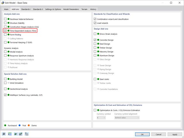
This article shows how the “Time-Dependent Analysis” add-on is integrated in RFEM 6 and RSTAB 9. It describes how to define input data such as the time-dependent characteristics of the material, how to determine the type of analysis and how to specify loading times.

The “Modal Analysis” add-on in RFEM 6 allows you to perform modal analysis of structural systems, thus determining natural vibration values such as natural frequencies, mode shapes, modal masses, and effective modal mass factors. These results can be used for vibration design, as well as for further dynamic analyses (for example, loading by a response spectrum).

In RFEM 6 it is possible to define multilayer surface structures with the help of the “Multilayer Surfaces” add-on. Hence, if you have activated the add-on in the model’s Base Data, it is possible to define layer structures of any material model. You can also combine material models of, for example, isotropic and orthotropic materials.

This article will show you a practical example of how to determine critical load factors and corresponding mode shapes in RFEM 6.

Modal analysis is the starting point for the dynamic analysis of structural systems. You can use it to determine natural vibration values such as natural frequencies, mode shapes, modal masses, and effective modal mass factors. This outcome can be used for vibration design, and it can be used for further dynamic analyses (for example, loading by a response spectrum).

You can model and analyze masonry structures in RFEM 6 with the Masonry Design add-on that employs the finite element method for the design. Complex masonry structures can be modeled, and static and dynamic analysis can be performed, given that a nonlinear material model is implemented in the program to display the load-bearing behavior of masonry and the different failure mechanisms. You can enter and model masonry structures directly in RFEM 6 and combine the masonry material model with all common RFEM add-ons. In other words, you can design entire building models in connection with masonry.

In accordance with Sect. 6.6.3.1.1 and Clause 10.14.1.2 of ACI 318-19 and CSA A23.3-19, respectively, RFEM effectively takes into consideration concrete member and surface stiffness reduction for various element types. Available selection types include cracked and uncracked walls, flat plates and slabs, beams, and columns. The multiplier factors available within the program are taken directly from Table 6.6.3.1.1(a) and Table 10.14.1.2.

Steel has poor thermal properties in terms of fire resistance. The thermal expansion for increasing temperature is very high compared to that of other building materials, and might result in effects that were not present in the design at normal temperature due to restraint in the component. As temperature increases, steel ductility increases, whereas its strength decreases. Since steel loses 50% of its strength at temperature of 600 °C, it is important to protect components against fire effects. In the case of protected steel components, the fire resistance duration can be increased due to the improved heating behavior.

The stability checks for the equivalent member design according to EN 1993-1-1, AISC 360, CSA S16, and other international standards require consideration of the design length (that is, the effective length of the members). In RFEM 6, it is possible to determine the effective length manually by assigning nodal supports and effective length factors or, on the other hand, by importing it from the stability analysis. Both options will be demonstrated in this article by determining the effective length of the framed column in Image 1.

This article describes how a flat slab of a residential building is modeled in RFEM 6 and designed according to Eurocode 2. The plate is 24 cm thick and is supported by 45/45/300 cm columns at distances of 6.75 m in both the X and Y directions (Image 1). The columns are modeled as elastic nodal supports by determining the spring stiffness based on the boundary conditions (Image 2). C35/45 concrete and B 500 S (A) reinforcing steel are selected as the materials for the design.

RFEM and RSTAB can calculate the critical load factor for each load case (LC) and each load combination (CO) in the case of a geometrically nonlinear calculation (second-order analysis and following).
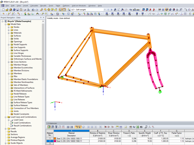
In RFEM and RSTAB, you can simulate extensive complex models from different materials in one computing environment.

The RF-STABILITY add-on module determines any critical load factors, effective lengths, and eigenvectors of RFEM models. Stability analyses can be carried out by various eigenvalue methods, the advantages of which depend on the structural system as well as computer configurations.

In RF‑TENDON and RF‑TENDON Design, you can review and adjust the code‑dependent factors, calculation parameters, and calculation methods using the "Code" button. You can display the settings and adjustment options according to a chapter of a code, selecting the "Grouping" option in the dialog box.

In the case of using slow‑curing concrete (usually for thick components), you can reduce the calculated minimum reinforcement by a factor of 0.85 to apply the load due to restraint, according to EN 1992‑1‑1, Section 7.3.2. However, a precondition for reduction is that the characteristic value of the strength development r = fcm2 / fcm28 does not exceed 0.3. Other key requirements for the application of this reinforcement reduction are specified explicitly in the final planning documents.
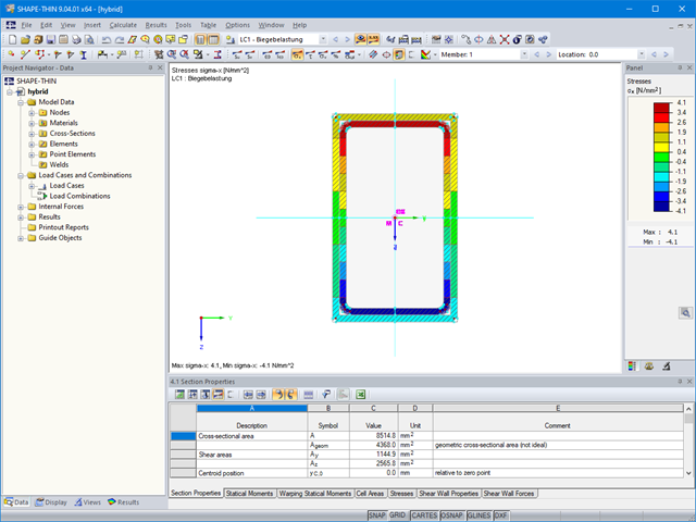
The material allocation for hybrid SHAPE‑THIN cross‑sections can be selected easily in RFEM and RSTAB. The prerequisite for this is the allocation of different materials to the cross‑section elements in SHAPE‑THIN.

In RFEM and RSTAB, you can visually check or display the materials used for members in the wireframe and solid models.

In the age of BIM, data exchange between the various disciplines of structural engineering is becoming increasingly important. Since each software has its own specifications with regard to the description of cross-sections and materials, RFEM and RSTAB offer a conversion table (mapping file).

In RF-/FOUNDATION Pro, the user can freely select the proportion of the relieving soil pressure by means of the factor kred.
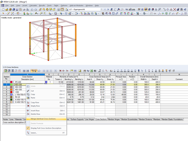
When modeling more complex structures with an increased degree of repetition, identical material and cross-section definitions often occur.

In the "Edit Load Cases and Combinations" dialog box, you can combine different load cases in one load combination under the "Load Combinations" tab.