Introduction
You can calculate deformations and forces for statically determined and overdetermined structures using the finite element method. In order to get the solutions for the background equation system, which depends on the selected member cross-sections, lengths, and rotation, the geometric (for example, support) and load-technical (for example, structural load) constraints are required:
[K] ∙ {u} = {F}
where
[K] is the stiffness matrix,
{u} is the vector of nodal displacement,
{F} is the vector of nodal point loads.
Example: A spring with the spring constant K = 3 N/m is extended to u = 0.5 m due to the force F. Thus, the force F is 3 N/m ∙ 0.5 m = 1.5 N.
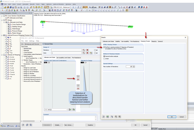
RF-/STEEL Warping Torsion determines forces and deformations of the specified sets of members again in a new calculation with seven degrees of freedom. However, this means that the extracted beam structures without boundary conditions are not computable. A calculation requires the corresponding geometric constraints in the form of a support definition and the load-technical constraints in the form of a member load.
Since the definitions of geometric supports are usually the same for various load situations, you can define nodal supports in Window 1.7 and elastic line supports in Window 1.13 on each node of the extracted beam structure. The program obtains the load-technical constraint from the load situations (load cases, load combinations, and result combinations) selected in Window 1.1. Since the load situations only include the loads for the entire structure in RFEM/RSTAB and not for the partial beam structure, it is necessary to define each load situation and set of members (parts of the structure) for the calculation of the partial structure in RF‑/STEEL Warping Torsion. This loading is determined at the beginning of the calculation, using the member internal forces of the global RFEM/RSTAB calculation in the module. These new member loads of the partial structure and the nodal supports already defined in the module are then used to determine the new forces and deformations according to the warping torsion analysis.
Determining Member Loads for Partial Structures
The design software performs the examination described in the following text for each partial structure and the associated load situation.
In order to determine the loads for the advanced analysis, the program uses the differential equation of the bending line:
where
w(x) is the function of the displacement,
M(x) is the function of the bending moment distribution,
EI(x) is the function of the bending stiffness using the longitudinal member axis (elastic modulus ∙ moment of inertia).
From the relationship between the bending line and the loading (Schwedler theorem), the program can derive load distributions qy(x), qz(x) using the bending moment My(x), Mz(x):
Bending moment M(x) = − EI(x) ∙ w''(x)
Shear force Q(x) = − (EI(x) ∙ w''(x))'
Load q(x) = (EI(x) ∙ w''(x))''
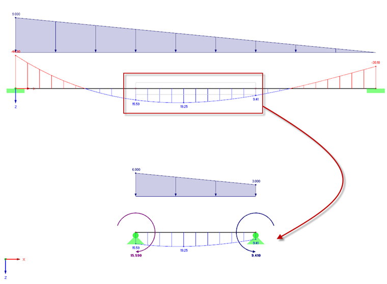
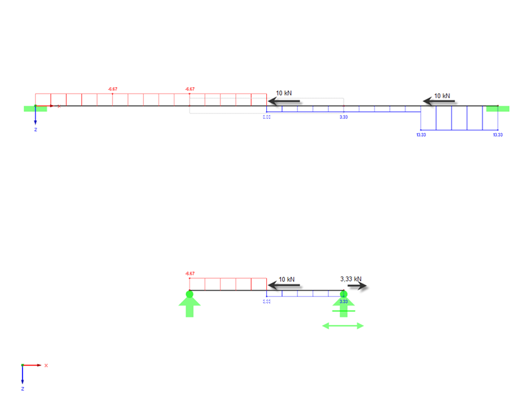
The transfer function determines the corresponding line loads for the extracted structure and the nodal loads in the distribution steps. The internal forces from the axial force and torsion are converted similarly and applied to the partial structure as loads. The shear forces should not be further considered in this analysis, as they result directly from the derivation of the bending moments and arise indirectly again from the new equivalent loads.
Using this procedure, the final partial structure will be loaded by internal forces similar to those resulting from the global calculation of the entire structure in RFEM/RSTAB, provided that the user-defined geometric constraints (supports) for the partial structure are applied to the partial structure as affine to the global effects of the structure. The following rules for defining supports must be respected:
1. The support must be applied as affine to the effect in the entire structure.
2. The partial structure must be statically determined or overdetermined.
3. In the case of partial structures conforming to the entire structure, it is necessary to specify the supports in the same way as for the entire structure.
4. Intermediate supports in the partial structure should always be defined with the same stiffness as for the entire structure.
5. For the extracted partial structures, the supports should be open on cutting points relating to the transferring bending moments around the respective rotational direction. In order to represent the distributions of axial and torsional forces caused by external loads, you have to open any edge support in and about the respective direction. Internal restraint forces on the partial structure are only considered partially (as an external load by the transfer function).
This transfer function can be used for load cases (LC), load combinations (CO), and result combinations (RC).
Conclusion
The new transfer function is a complex tool for determining loads on partial structures. Full integration in RF-/STEEL Warping Torsion allows you to realize the full potential of this feature. Thus, the load determination for the calculation according to seven degrees of freedom only depends on the selection of load situations to be analyzed.