35 Results
View Results:
Sort by:

Spreadsheet programs like MS EXCEL are very popular with engineers because they allow you to simply automatize your calculations and quickly output the results. Therefore, combining MS EXCEL used as a graphical interface with Dlubal's WebService API is an obvious choice. By using the free xlwings library for Python, you can control EXCEL, and read and write values. The functionality is described in the following, using an example.

Nodal releases are special objects in RFEM 6 that allow structural decoupling of objects connected to a node. The release is controlled by the release type conditions, which may also have nonlinear properties. This article will show the definition of nodal releases in a practical example.

This article will show you the Building Model add-on, which has been enhanced with one important advantage: calculating the center of mass and center of rigidity.

This article shows you how to create contacts between two or more parallel surfaces by controlling the transfer of forces between them.

The advantage of the RFEM 6 Steel Joints add-on is that you can analyze steel connections using an FE model for which the modeling runs fully automatically in the background. The input of the steel joint components that control the modeling can be done by defining the components manually, or by using the available templates in the library. The latter method is included in a previous Knowledge Base article titled “Defining Steel Joint Components Using the Library". The definition of parameters for the design of steel joints is the topic of the Knowledge Base article “Designing Steel Joints in RFEM 6".

You can use the Steel Joints add-on in RFEM 6 to create and analyze steel connections using an FE model. You can control the modeling of the connections via a simple and familiar input of components. Steel joint components can be defined manually, or by using the available templates in the library. The former method is included in a previous Knowledge Base article titled “A Novel Approach to Designing Steel Joints in RFEM 6". This article will focus on the latter method; that is, it will show you how to define steel joint components using the available templates in the program’s library.
In addition to the predefined models available as blocks in Dlubal Center | Blocks, it is possible to create new blocks and save them in the manner discussed in the Knowledge Base article "Saving Models as Blocks in RFEM 6".

Defining the appropriate effective length is crucial in obtaining the correct member design capacity. For X-bracing that is connected at the center, engineers often wonder if the full end-to-end length of the member shall be used, or whether using half of the length to where the members are connected is sufficient. This article outlines the recommendations given by the AISC and provides an example on how to specify the effective length of the X-braces in RFEM.

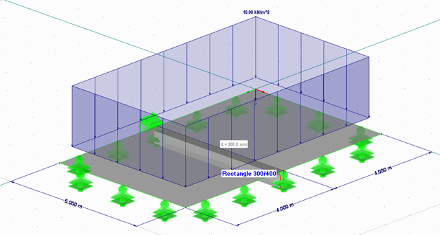
The punching shear design, in line with EN 1992-1-1, should be performed for slabs with a concentrated load or reaction. The node where the design of punching shear resistance is performed (that is, where there is a punching problem) is called a node of punching shear. The concentrated load at these nodes can be introduced by columns, concentrated force, or nodal supports. The end of the linear load introduction on slabs is also regarded as a concentrated load and therefore, the shear resistance at wall ends, wall corners, and ends or corners of line loads and line supports should be controlled as well.
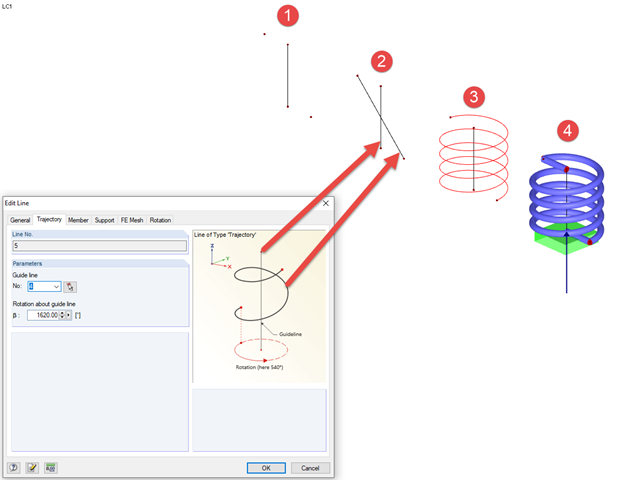
In RFEM, you can create screw lines using the "Trajectory" type line. To do this, you need a center line/guide line around which the line can be modeled, as well as a start and end point. Then, you can create a "Trajectory" type line between the start and end points; this initially appears as a straight line.

In CRANEWAY, the action of a rail as "statically effective" or "statically ineffective" is defined under "Rail‑Flange Connection" in the Details dialog box. This setting controls the calculation of the load introduction length according to EN 1993-6, Tab. 5.1.
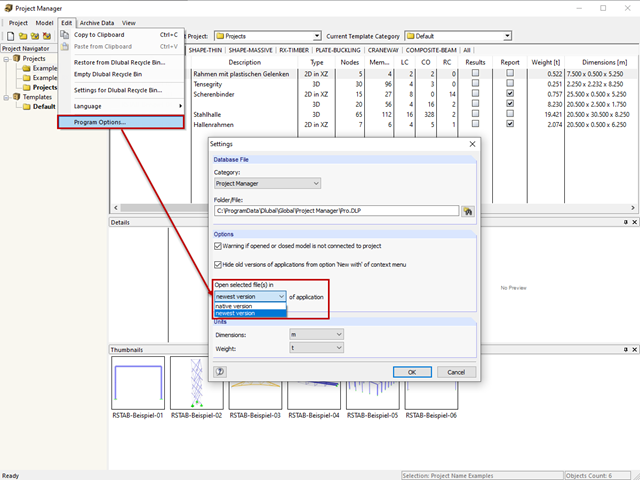
The network-capable Project Manager controls the projects of all Dlubal Software applications in one central location.

General thin-walled cross-sections often have asymmetrical geometries. The principal axes of such sections are then not parallel to the horizontally and vertically aligned axes Y and Z. When determining the cross-section properties, the angle α between the center-of-gravity axis y and the principal axis u is determined in addition to the principal axis-related moments of inertia.

In the RF-GLASS add-on module, 3D rendering is implemented to facilitate the definition of the support conditions. This interactive graphical visualization facilitates the input and control of line and nodal supports. However, the schematic display can also be selected, if necessary.
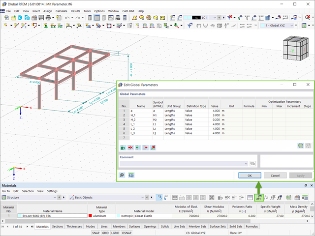
In the Formula Editor environment, you can specify any parameters (lengths, force values, and so on) to control load and geometry data in the modeling.

You can use the "Free Circular Load" option in RFEM to apply a partial uplift force to a cone‑shaped floor slab. It can be defined as linearly variable. The definition of center C and the outer boundary R can be specified easily, using the select function.
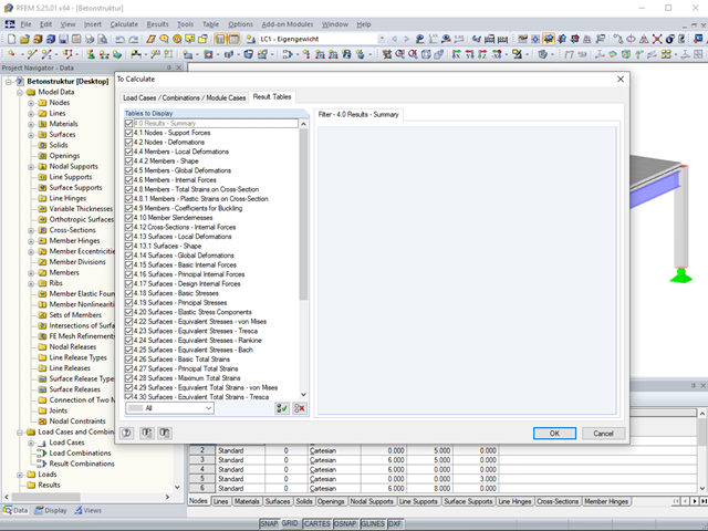
The "Result Tables" tab under "Calculation" → "To Calculate" controls which tables are available after the calculation.
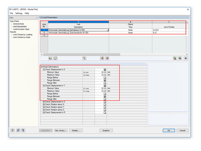
To control the lateral displacements of a model, you can use the RF-/LIMITS add‑on module. This add‑on module allows you to, for example, run a serviceability limit state analysis to find horizontal nodal deformations and to set it against a limit value.
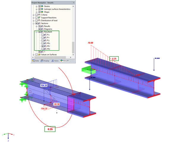
For control purposes, it is possible to display the resulting internal force in sections in RFEM. To illustrate this, the bending moment was selected in this example.
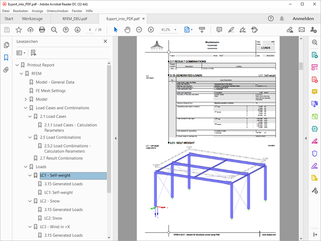
A PDF version of the printout report can be created in two ways. The most common way is to use a PDF printer that must be previously installed. The printer will be controlled like a real printer.
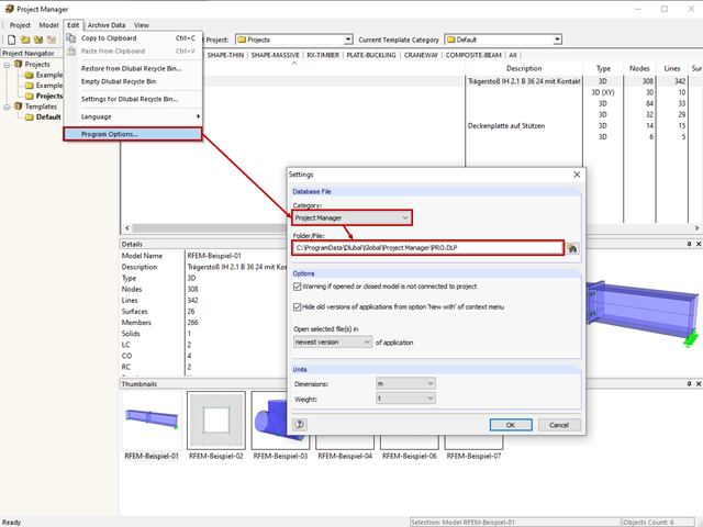
The network-capable Project Manager controls the projects of all Dlubal Software applications in one central location. The projects are linked to the folders on the hard disk.
The simplest way to model a bolt connection in RFEM 5 is to define a node in the center of a hole, then connect it by means of internal members to the surface.
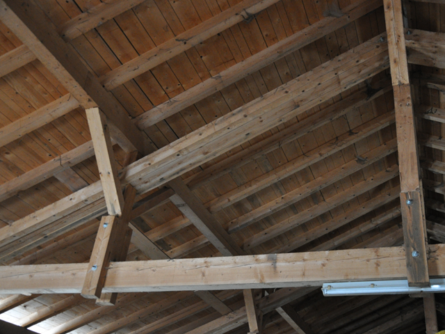
When modeling frame structures, RFEM and RSTAB provide various options for controlling the transfer of internal forces and moments at the connection points of members. You can use the member types to determine whether only forces act on the connected members, or whether moments act on them as well. In addition, you can use hinges to exclude specific internal forces from the transfer. One special form is scissor hinges, which allow for realistic modeling of roof structures, for example.
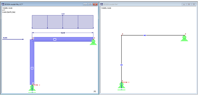
The beam is resting on the column, and the beam ends at the outer edge of the column. These requirements can be fulfilled easily in an architectural model with solids. In member analysis, simplified line models are used in which center lines meet in a common node. In this article, the influence of member eccentricities on the determination of internal forces is shown on three simple models.
When performing control calculations and comparing the internal forces and the resulting required reinforcement of downstand beams, large differences can occur. Although the same load assumptions and spans are applied, some programs or the manual calculation display very different internal forces compared to the FEA model. The differences already occur in the case of the centric member and without considering the internal forces' components from the possible effective slab widths.
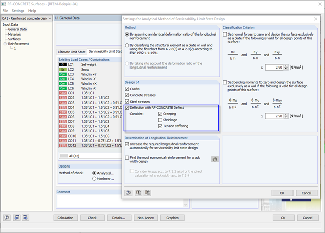
Performing serviceability limit state design also includes taking into account the allowable deformation. Calculating the deformation of reinforced concrete components depends on whether or not the observed cross-section cracks under the applied loading. The governing control parameter in RF-CONCRETE Deflect is the distribution coefficient ζ.

The story drift of a building provides valuable information about its structural behavior under seismic loads. These could cause large horizontal deformations and even instabilities. Some standards, therefore, call for a check of the story drift in its center of gravity. It indicates, for example, if a second-order analysis (P-Δ effect) is necessary.
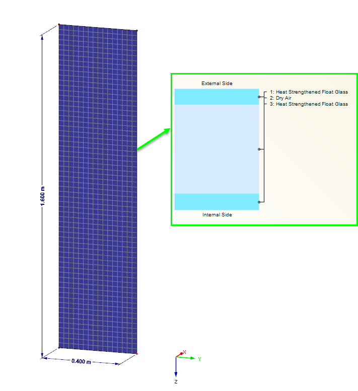
Loading panes of insulating glass due to climatic effects are clearly regulated in DIN 18008. In the case of the corresponding pane geometry, this load type can also govern for the ultimate limit state design. The FE design on the entire structure with the space between panes represented as the volume of a gas provides exact results for the analysis. However, a plausibility check is also becoming increasingly important. This article shows various options for performing these checks.
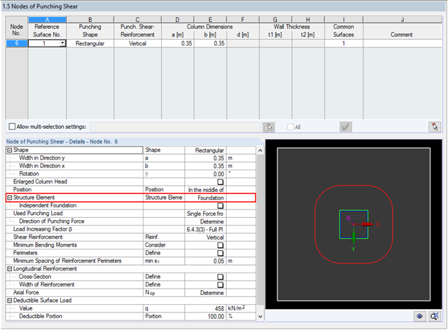
The RF‑PUNCH Pro add‑on module allows you to perform the punching shear design of floor slabs and foundation plates according to EN 1992‑1‑1. In the case of a floor slab, the basic control perimeter is applied according to 6.4.2 (1), EN 1992‑1‑1 [1] at a distance of 2d from the loaded area.

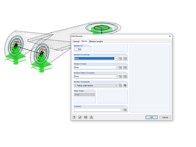
If you want to connect members tangentially to a curved member or a curved surface in RFEM, it is necessary to define the member rotation of the connected members. In order to avoid manual determination, you can display the center point of the curved line and place a node on it. Then, you can select the "Member Rotation via Help node" option and specify the relevant help nodes. Thus, the members are rotated automatically in the defined plane (x-z in our example) and the top edge of the rotated cross-section is parallel to the tangent of the curved line.