69 Results
View Results:
Sort by:

This article explains how the calculation in the initial stiffness analysis in Steel Joints works.

In this article, a lap joint of a ZL purlin on a monopitch roof is modeled and designed using the Steel Joints add-on, and compared with the load-bearing capacity table of the manufacturer.

Steel connections in RFEM 6 can be created by simply entering predefined components in the Steel Joints add-on. The collection of these components is constantly being improved to make your work even easier even when modeling steel connections. In this article, the connection plate component is introduced as a component recently added to the add-on's library.

In RFEM 6, it is possible to define line welds on lines between surfaces and calculate the weld stresses using the Stress-Strain Analysis add-on. This article will show you how to do it.

The advantage of the RFEM 6 Steel Joints add-on is that you can analyze steel connections using an FE model for which the modeling runs fully automatically in the background. The input of the steel joint components that control the modeling can be done by defining the components manually, or by using the available templates in the library. The latter method is included in a previous Knowledge Base article titled “Defining Steel Joint Components Using the Library". The definition of parameters for the design of steel joints is the topic of the Knowledge Base article “Designing Steel Joints in RFEM 6".

Steel connections in RFEM 6 are defined as an assembly of components. In the new Steel Joints add-on, universally applicable basic components (plates, welds, auxiliary planes) are available for entering complex connection situations. The methods with which connections can be defined are considered in two previous Knowledge Base articles: “A Novel Approach to Designing Steel Joints in RFEM 6" and “Defining Steel Joint Components Using the Library".

You can use the Steel Joints add-on in RFEM 6 to create and analyze steel connections using an FE model. You can control the modeling of the connections via a simple and familiar input of components. Steel joint components can be defined manually, or by using the available templates in the library. The former method is included in a previous Knowledge Base article titled “A Novel Approach to Designing Steel Joints in RFEM 6". This article will focus on the latter method; that is, it will show you how to define steel joint components using the available templates in the program’s library.

One of the innovations in RFEM 6 is the approach to designing steel connections. In contrast to RFEM 5, where the design of steel joints is based on an analytical solution, the Steel Joints add-on in RFEM 6 offers an FE solution for steel connections.

If members aligned in space meet in a node, the local x- or y-axes of the members do not lie in one plane, since the local z-axes are aligned in the plane of gravity.

RF-CONCRETE Members also includes the design of a shear joint. In order to perform this design, you should select the "Shear joint available" check box in Window 1.6, Shear Joint tab.
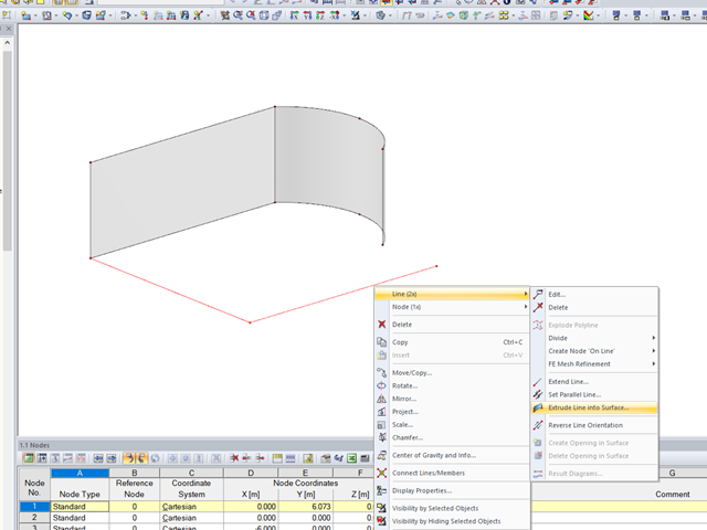
In RFEM, the function is implemented to generate a surface automatically from lines perpendicular to the work plane.

- 000945
- Add-on Modules
- RF-FRAME-JOINT Pro 5
-
- JOINTS Steel | Column Base 8
- JOINTS Steel | DSTV 8
- JOINTS Steel | Pinned 8
- JOINTS Steel | Rigid 8
- JOINTS Steel | SIKLA 8
- JOINTS Steel | Tower 8
- JOINTS Timber | Steel to Timber 8
- JOINTS Timber | Timber to Timber 8
- RF-JOINTS Steel | SIKLA 5
- RF-JOINTS Steel | Column Base 5
- RF-JOINTS Steel | DSTV 5
- RF-JOINTS Steel | Pinned 5
- RF-JOINTS Steel | Rigid 5
- RF-JOINTS Steel | Tower 5
- RF-JOINTS Timber | Steel to Timber 5
- RF-JOINTS Timber | Timber to Timber 5
- FRAME-JOINT Pro 8
- Steel Structures
- Timber Structures
- Steel Connections
- Eurocode 3
- Eurocode 5
In addition to the result tables, you can create three-dimensional graphics in RF‑/FRAME‑JOINT Pro and RF‑/JOINTS. This is a realistic representation of a connection to scale.

The joint type "Main member only" in RF‑/JOINTS Timber - Steel to Timber can also be applied for more than one connected member.

In the case of wall-like load-bearing behavior of the cross-laminated timber plate, special attention must be paid to the shear deformation in the plane of the pane and thus, in particular, to the displaceability of the fasteners.
The RF‑/JOINTS add‑on modules are equipped with a graphical window that shows all the structural components of the connection. There, you can use the mouse functions known from RFEM and RSTAB to zoom, move, or rotate the view.

In EN 1993-1-1, the General Method was introduced as a design format for stability analyses that can be applied to planar systems with arbitrary boundary conditions and variable structural height. The design checks can be performed for loading in the main load-bearing plane and simultaneous compression. The stability cases of lateral-torsional buckling and flexural buckling are analyzed from the main supporting plane; that is, about the weak component axis. Therefore, the issue often arises as to how to design, in this context, flexural buckling in the main load-bearing plane.

In timber design, beams are often built from several timber elements. The individual elements can be connected with glue, nails, bolts, or dowels. A glued connection is to be assumed as rigid. In the case of dowel‑type fasteners, the joint is compliant (slip joint), and the cross‑section properties of the connected elements cannot be fully applied.
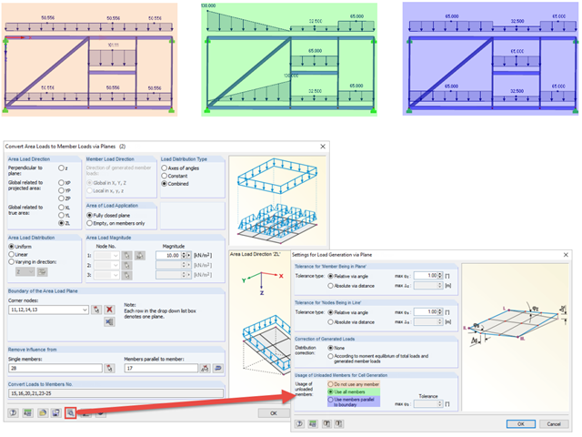
When generating member loads via plane, the program generates cells internally. These cells significantly influence the created member loads.

With the orthotropic elastic-plastic material model, you can calculate solids with plastic material properties in RFEM 5 and evaluate them according to the Tsai‑Wu failure criterion. The Tsai-Wu criterion is named for Stephen W. Tsai and Edward M. Wu, who published it in 1971 for plane stress states.
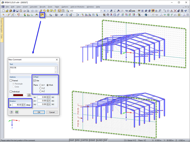
In RFEM and RSTAB, you can add a comment to model objects in the graphic. When inserting a comment, the origin of the current work plane automatically jumps temporarily to the same plane in which the comment is placed. This prevents comments from being accidentally placed very far from the object.
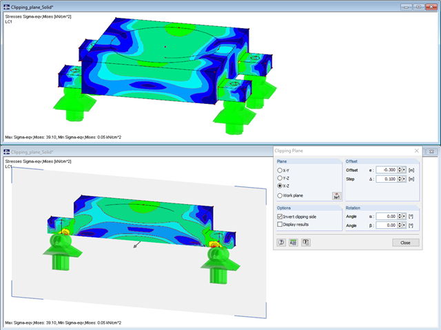
The "Clipping Plane" function allows you to define any section through the model.
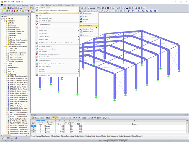
In RFEM 5 and RSTAB 8, you can now create a work plane by simply selecting three points. It is no longer necessary to create a user-defined coordinate system.
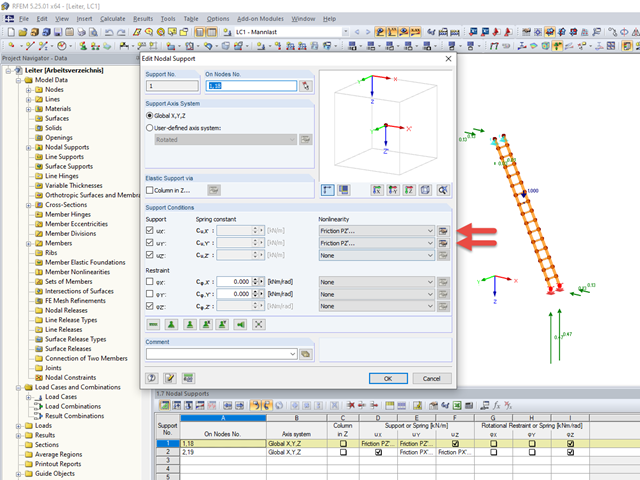
Friction plays an important role in practice. Without friction, the brakes of cars would be useless, objects on inclined planes would just slide away, and prestressed bolt connections would be impossible.
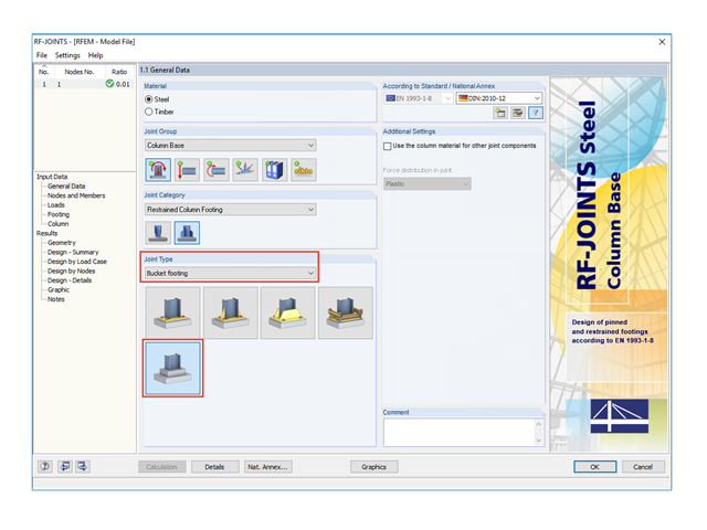
In the RF‑/JOINTS Steel - Column Base add-on module, you can also design restrained column bases in bucket foundations.

Table 3.1 of EN 1993‑1‑8:2010‑12 defines the nominal values of the yield strength and the ultimate limit strength of bolts. The bolt classes given here are 4.6, 4.8, 5.6, 5.8, 6.8, 8.8, 10.9. The note for this table states that the National Annex may exclude certain bolt classes. For the NA of Germany, these are the bolt classes 4.8, 5.8, and 6.8.
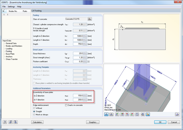
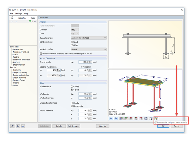
For structural reasons, it may be necessary for a base plate not to be set centrically on a foundation. Therefore, an eccentric arrangement of the base plate is possible in RF‑/JOINTS Steel - Column Base by entering the parameters for the respective direction in Window 1.4.

Closed circular cross-sections are ideal for welded truss structures. The architecture of such constructions is popular when designing transparent roofs. This article shows the special features of the connection design using hollow sections.

Designing rigid end plate connections is difficult for four-row connection geometries and multi-axis bending stresses, because there are no official design methods.
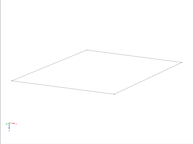
This example describes a definition of a planar surface by four nodes that have been imported and seem to lie in a common plane. In reality, they are not exactly in one plane due to (for example) a previous modeling error of a few millimeters. When trying to create a planar surface, the error message "Error in the surface definition! The nodes do not lie in a common plane." appears.
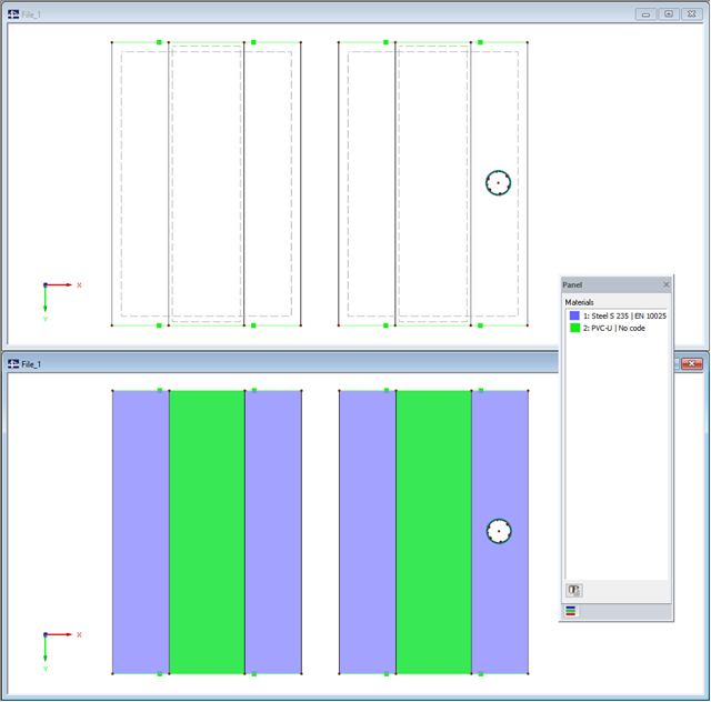
When modeling with finite elements, sooner or later you come up with the question of how two surfaces (2D elements) lying on top of each other can be modeled. Hence, both surfaces are often modeled in the same plane. The possible consequences of this approach, and whether there are better solutions, are described below.