Display Options for 3D Graphics
Technical Article
In addition to the result tables, you can create three-dimensional graphics in RF‑/FRAME‑JOINT Pro and RF‑/JOINTS. This is a realistic representation of the connection to scale.
For views in the direction of the main axes, click the corresponding icon. You can also view the graphic from any other perspective: To do this, move the cursor over the graphical window while holding down the middle mouse button and the Ctrl key.
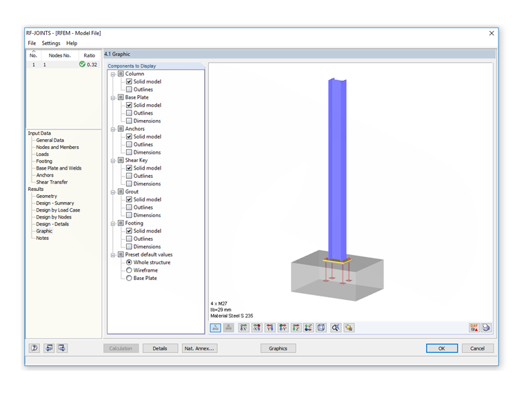
A special feature allows you to separately display or hide the individual components of the connection as well as dimension lines and weld details, for example. The selection is possible in the navigator to the left of the graphic.
Using these options, you can represent a connection very clearly. You can print the individual views, including dimensions and annotations, directly to the printout report.
Author

Bastian Ackermann, M.Sc.
Customer Support
Mr. Ackermann provides technical support for customers of Dlubal Software and takes care of their requests.
Keywords
Links
Write Comment...
Write Comment...
Contact Us
Do you have any further questions or need advice? Contact us via phone, email, chat or forum or find suggested solutions and useful tips on our FAQ page, available 24/7.

New
Evaluating and Documenting Steel Joints Analysis Results in RFEM 6
With the RFEM 6 add-on Steel Joints, you can analyze steel connections by using an FE model. This article demonstrates how to evaluate and document the steel joints analysis results.

New
- The design of the connection components is performed according to Eurocode EN 1993-1-8
- After activating the Add-on, the design situations for Steel Connections must be activated in the "Load cases and Combinations" dialog box
- For the design of the connection stability (Buckling), it is necessary to have the Add-on Structure Stability activated
- The calculation can be started via the table or via the icon in the top bar
-
How do I set a release for warping?
- How can I define a warping spring or a warping restraint?
- At which point on a cross-section are the supports and loads assumed for the calculation with warping torsion?
- The limit stress is activated, but my stress ratio is “non-designable” in the Stress-Strain Analysis add-on. What could be the reason?
- How can I deactivate the 7th degree of freedom for certain members or cross-sections only?
- How can I define a warping spring or a warping restraint?