25 Results
View Results:
Sort by:

The Construction Stages Analysis (CSA) add-on allows for the design of member, surface, and solid structures in RFEM 6 considering the specific construction stages associated with the construction process. This is important since buildings are not constructed all at once, but by gradually combining individual structural parts. The single steps in which structural elements, as well as loads, are added to the building are called construction stages, whereas the process itself is called a construction process.
Thus, the final state of the structure is available upon completion of the construction process; that is, all the construction stages. For some structures, the influence of the construction process (that is, all the individual construction stages) might be significant and it should be considered so that errors in the calculation are avoided. A general overview of the CSA add-on is given in the Knowledge Base article titled “Consideration of Construction Stages in RFEM 6”.

The design of cross-sections according to Eurocode 3 is based on the classification of the cross-section to be designed in terms of classes determined by the standard. The classification of cross-sections is important, since it determines the limits of resistance and rotation capacity due to local buckling of cross-section parts.

The effects due to snow load are described in the American standard ASCE/SEI 7-16 and in Eurocode 1, Parts 1 through 3. These standards are implemented in the new RFEM 6 program and the Snow Load Wizard, which serves to facilitate the application of snow loads. In addition to this, the most recent generation of the program allows the construction site to be specified on a digital map, thus allowing the snow load zone to be imported automatically. These data are, in turn, used by the Load Wizard to simulate the effects due to the snow load.

The calculation of complex structures by means of finite element analysis software is generally performed on the entire model. However, the construction of such structures is a process carried out in multiple stages where the final state of the building is achieved by combining the separate structural parts. To avoid errors in the calculation of overall models, the influence of the construction process must be considered. In RFEM 6, this is possible using the Construction Stages Analysis (CSA) add-on.
If you want to only change a few geometry parameters in a model, it is not always necessary to remove these structural parts and redefine them.
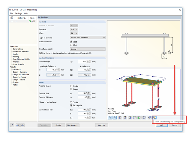
The RF‑/JOINTS add‑on modules are equipped with a graphical window that shows all the structural components of the connection. There, you can use the mouse functions known from RFEM and RSTAB to zoom, move, or rotate the view.
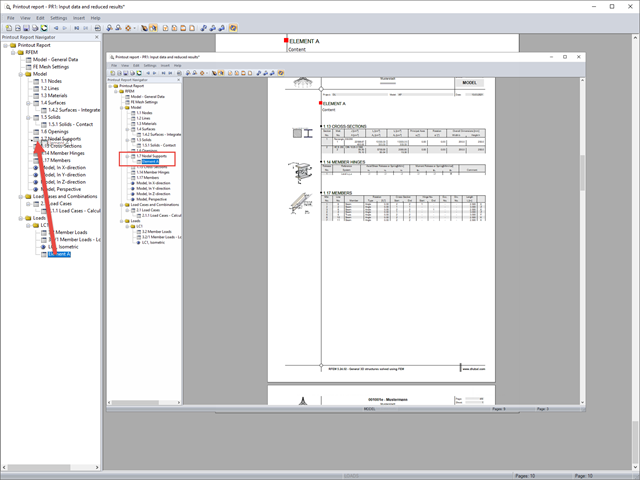
If you want to move individual elements or entire chapters in the printout report, there are various options.
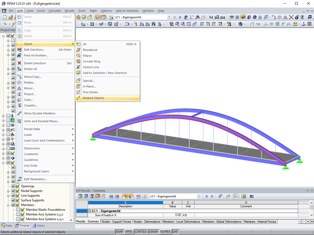
Sometimes it is necessary to add related objects, such as nodes and lines of a surface, to the selection in order to edit parts of the model.
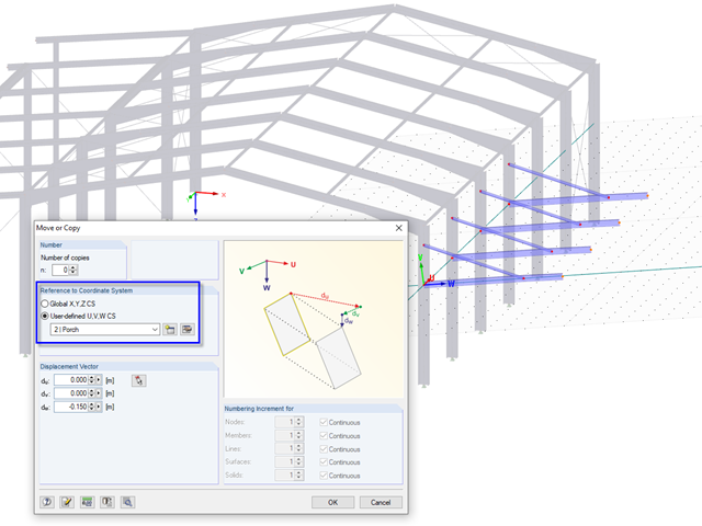
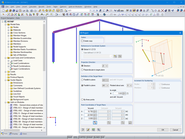
In RFEM and RSTAB, it is possible to move or copy models or parts of the model in a user-defined coordinate system. To use this option, a user-defined coordinate system must be available, of course.

The classification of cross-sections according to EN 1993-1-1 using Table 5.2 is a simple method for designing the local buckling of cross-section parts. For cross-sections of cross-section class 4, it is then necessary to determine the effective cross-section properties according to EN 1993-1-5 in order to consider the influence of local buckling in the ultimate limit state designs.

The classification of cross-sections according to EN 1993‑1‑1 and EN 1993‑1‑5 can be carried out automatically in the RF‑/STEEL EC3 add-on module. The maximum c/t ratios are specified in the standard for straight cross-section parts. There are no normative specifications for curved cross-section parts; therefore, the cross-section classification cannot be performed for these cross-section parts.

The classification of cross-sections is intended to determine the limits of resistance and rotational capacity due to local buckling of cross-section parts. In EN 1999‑1‑1, 6.1.4.2 (1), four classes are defined.
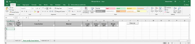
The parts lists give information about which and how many parts are necessary for creating a building. They form the basis for identifying the needs and purchasing the components. Parts lists can be created in design modules, such as RF‑/STEEL EC3, RF‑/TIMBER Pro, and so on. Furthermore, a customized parts list can be created with the RF-COM/RS-COM interface.
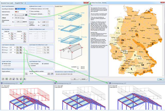
Eurocode 1, Parts 1 to 3, and American standard ASCE/SEI 7-16 describe the general effects due to snow loads. The load applications for duopitch, monopitch, and flat roofs required by the standards are stored in a tool in RFEM and RSTAB so that these effects can be generated easily.
Part 4.1 of this article series describes the connection of the RF‑/STEEL EC3 add‑on module; the members and load combinations to be designed were already defined. This section will focus on the optimization of cross‑sections in the module and the transfer to RFEM. The elements already explained in the previous parts are not described again.

When designing bending-resistant connections from I-beams, the connection is dissolved into the individual parts. For these basic components of a joint, there are separate formula calculators for load-bearing capacity and stiffness. In RFEM and RSTAB, frame joints can be designed using the RF-/FRAME-JOINT Pro add-on module.

According to Clause 7.3.2 (2), standard DIN EN 1992-1-1 requires: "In profiled cross‑sections like T‑beams and box girders, the minimum reinforcement should be determined for the individual parts of the section (webs, flanges)." In the case of a floor beam with a T‑section, the minimum reinforcement should be determined for both flanges and the web if the corresponding partial cross‑sections are in the tension area. Image 01 shows the division into partial cross-sections.
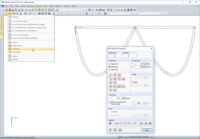
In addition to arcs and circles, SHAPE-THIN 8.xx allows you to model the following curved cross-section parts: ellipses, elliptical arcs, parabolas, hyperbolas, splines, NURBS (non-uniform rational B-Spline).
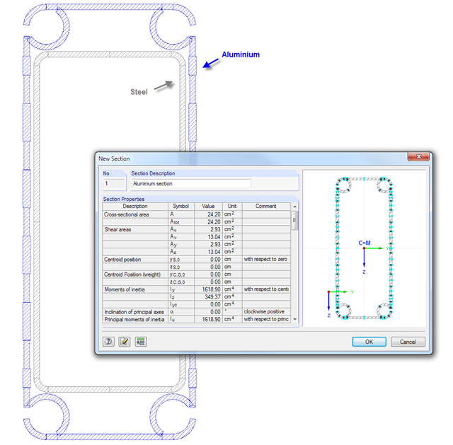
SHAPE‑THIN cross‑section properties software provides the option to combine cross‑section parts in a "section" and display the cross‑section properties. Thus, you can determine the values of the individual components in a composite cross‑section.
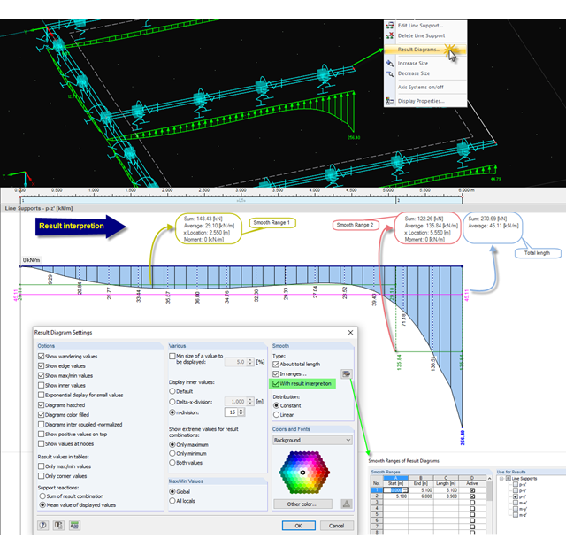
When evaluating results in the smooth state, you can display the average and sum values. This option is also available for parts of a line, a section, and so on. By importing the graphic into the printout report, you can document these values in the structural analysis.

Prior to the analysis of steel cross‑sections, the cross‑sections are classified according to EN 1993‑1‑1, Sec. 5.5, with respect to their resistance and rotation capacity. Thus, the individual cross-section parts are analyzed and assigned to Classes 1 to 4. The cross-section classes are determined subsequently and usually assigned to the highest class of the cross-section parts. If plastic resistance is to be applied to further design of cross-sections of Class 1 and Class 2, you can analyze the elastic resistance of cross-sections as of Class 3. In the case of cross-sections of Class 4, local buckling occurs even before reaching the elastic moment. In order to take this effect into account, you can use effective widths. This article describes the calculation of the effective cross-section properties in more detail.
The RF-/STEEL EC3 add‑on module performs a detailed cross‑section classification on each design before the design is carried out. Thus, the susceptibility to local buckling of all cross-section parts is evaluated. The defined cross-section class has an effect on the resistance and rotational capacity determination.
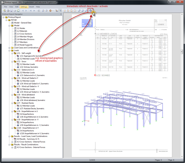
Input data and results can be clearly arranged in a printout report. The contents are listed in compliance with the program-specific definition. If the order of the contents does not correspond to your requirements, you can move the individual parts anywhere in the printout report.
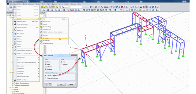
In RFEM and RSTAB, there are several ways to select a part of the structural model for further processing. The most frequently used selection option is definitely "selection using window". Depending on the size of the structure, the simultaneous selection of several areas of the structure using this option may be time-consuming, since the unwanted model parts are selected as well.
For recurring elements such as certain structural components or standard parts, you can use the parametrization of a basic model. In the program, the main elements do not represent components but the corresponding node and therefore, they have to be parameterized. For example, a member is not defined by the length, but by the start and end nodes. In this way of modeling, complex formulas may occur especially in the case of three-dimensional structures.