76 Results
View Results:
Sort by:

The data exchange between RFEM 6 and Allplan can be done using various file formats. This article describes the data exchange of a determined surface reinforcement using the ASF interface. This allows you to display the RFEM reinforcement values as level curves or colored reinforcement images in Allplan.

Both the determination of natural vibrations and the response spectrum analysis are always performed on a linear system. If nonlinearities exist in the system, they are linearized and thus not taken into account. They are caused by, for example, tension members, nonlinear supports, or nonlinear hinges. This article shows how you can handle them in a dynamic analysis.

Steel connections in RFEM 6 are defined as an assembly of components. In the new Steel Joints add-on, universally applicable basic components (plates, welds, auxiliary planes) are available for entering complex connection situations. The methods with which connections can be defined are considered in two previous Knowledge Base articles: “A Novel Approach to Designing Steel Joints in RFEM 6" and “Defining Steel Joint Components Using the Library".

If members aligned in space meet in a node, the local x- or y-axes of the members do not lie in one plane, since the local z-axes are aligned in the plane of gravity.

A member's boundary conditions decisively influence the elastic critical moment for lateral-torsional buckling Mcr. The program uses a planar model with four degrees of freedom for its determination. The corresponding coefficients kz and kw can be defined individually for standard-compliant cross-sections. This allows you to describe the degrees of freedom available at both member ends due to the support conditions.

In the case of using slow‑curing concrete (usually for thick components), you can reduce the calculated minimum reinforcement by a factor of 0.85 to apply the load due to restraint, according to EN 1992‑1‑1, Section 7.3.2. However, a precondition for reduction is that the characteristic value of the strength development r = fcm2 / fcm28 does not exceed 0.3. Other key requirements for the application of this reinforcement reduction are specified explicitly in the final planning documents.
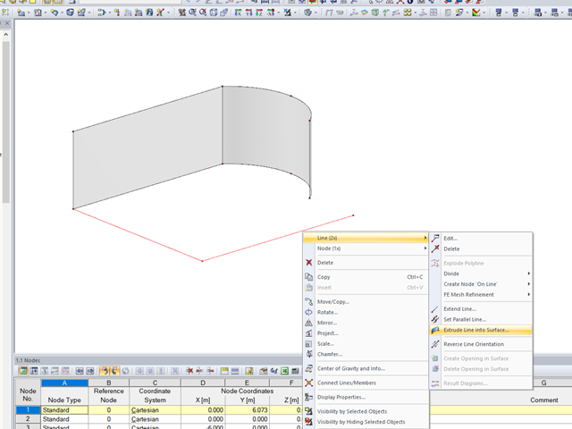
In RFEM, the function is implemented to generate a surface automatically from lines perpendicular to the work plane.
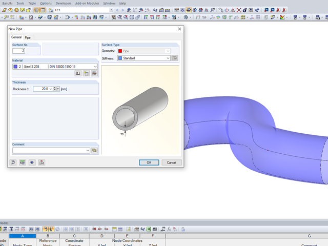
It may become necessary to analyze pipe cross‑sections as surface models in plant engineering in particular, but also when analyzing details of structural systems. For this purpose, RFEM offers the option to create pipe cross‑sections automatically by means of a line.

In the default setting, the cross-section class for each member and load case is determined automatically in the design modules. In the input window of the cross sections, however, the user can also specify the cross-section class manually; for example, if local buckling is excluded by the design.

In the case of wall-like load-bearing behavior of the cross-laminated timber plate, special attention must be paid to the shear deformation in the plane of the pane and thus, in particular, to the displaceability of the fasteners.

DXF layers of ground plans cannot be used directly in FEA programs because only the outer contours of the elements (walls, ceilings, and so on) are available in the drawing. The FEM programs require system axes, but only the outer contours of the elements (walls, ceilings, and so on) are available in the DXF drawing.
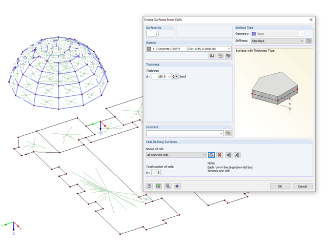
If you have imported a DXF file in RFEM or you need to add a membrane to an existing member structure, you can use the function "Tools" → "Generate Model - Surfaces" → "Surfaces from Cells", and thus quickly create planar surfaces.

In EN 1993-1-1, the General Method was introduced as a design format for stability analyses that can be applied to planar systems with arbitrary boundary conditions and variable structural height. The design checks can be performed for loading in the main load-bearing plane and simultaneous compression. The stability cases of lateral-torsional buckling and flexural buckling are analyzed from the main supporting plane; that is, about the weak component axis. Therefore, the issue often arises as to how to design, in this context, flexural buckling in the main load-bearing plane.

For the stability design of members and sets of members with a uniform cross-section, you can use the equivalent member method according to EN 1993-1-1, 6.3.1 to 6.3.3. However, as soon as a tapered cross-section is available, this method can no longer be used, or only used to a limited extent. The RF-/STEEL EC3 add-on module can automatically recognize these cases and switch to the general method.

In RFEM, surfaces are automatically connected if they have common boundary lines. If the definition line of a surface is lying in another surface, the line is automatically integrated into the surface, provided that it is a planar surface. For quadrangle surfaces, however, automatic object detection would be relatively time-consuming. For this reason, the corresponding function is deactivated. The integrated objects must be specified manually.
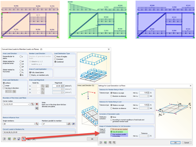
When generating member loads via plane, the program generates cells internally. These cells significantly influence the created member loads.

In RFEM 5 and RSTAB 8, it is possible to assign nonlinearities to member hinges. In addition to the nonlinearities "Fixed if" and "Partial activity", you can select "Diagram". If you select the "Diagram" option, you have to specify the according settings for the activity of the member hinge. For the individual definition points, it is necessary to specify the abscissa and ordinate values (deformations or rotations and the according internal forces) that define the hinge.

With the orthotropic elastic-plastic material model, you can calculate solids with plastic material properties in RFEM 5 and evaluate them according to the Tsai‑Wu failure criterion. The Tsai-Wu criterion is named for Stephen W. Tsai and Edward M. Wu, who published it in 1971 for plane stress states.

In the case of open cross-sections, the torsional load is removed mainly via secondary torsion, since the St. Venant torsional stiffness is low compared to the warping stiffness. Therefore, warping stiffeners in the cross-section are particularly interesting for the lateral-torsional buckling analysis, as they can significantly reduce the rotation. For this, end plates or welded stiffeners and sections are suitable.

RFEM 5 allows you to use many different member nonlinearities for designing a model. In the following text, we look at an example of the use of the "slippage" member nonlinearity. The example is a simplified model of a concrete manhole with a square plan view.

- 000487
- Modeling | Structure
- RFEM 5
-
- RF-STEEL 5
- RF-STEEL AISC 5
- RF-STEEL AS 5
- RF-STEEL BS 5
- RF-STEEL CSA 5
- RF-STEEL EC3 5
- RF-STEEL GB 5
- RF-STEEL HK 5
- RF-STEEL IS 5
- RF-STEEL NBR 5
- RF-STEEL NTC-DF 5
- RF-STEEL SANS 5
- RF-STEEL SIA 5
- RF-STEEL SP 5
- RF-ALUMINUM 5
- RF-ALUMINUM ADM 5
- RSTAB 8
- STEEL 8
- STEEL AISC 8
- STEEL AS 8
- STEEL BS 8
- STEEL CSA 8
- STEEL EC3 8
- STEEL GB 8
- STEEL HK 8
- STEEL IS 8
- STEEL NBR 8
- STEEL NTC-DF 8
- STEEL SANS 8
- STEEL SIA 8
- STEEL SP 8
- ALUMINUM 8
- ALUMINUM ADM 8
- Steel Structures
- Process Manufacturing Plants
- Stairway Structures
- Structural Analysis & Design
- Eurocode 3
- ANSI/AISC 360
- SIA 263
- IS 800
- BS 5950-1
- GB 50017
- CSA S16
- AS 4100
- SP 16.13330
- SANS 10162-1
- ABNT NBR 800
- ADM
The support conditions of a beam subjected to bending are essential for its resistance to lateral-torsional buckling. If, for example, a single-span beam is held laterally in the middle of the span, the deflection of the compressed flange can be prevented, and a two-wave eigenmode can be enforced. The critical lateral-torsional buckling moment is increased significantly by this additional measure. In the add-on modules for member design, different types of lateral supports on a member can be defined using the "Intermediate supports" input window.
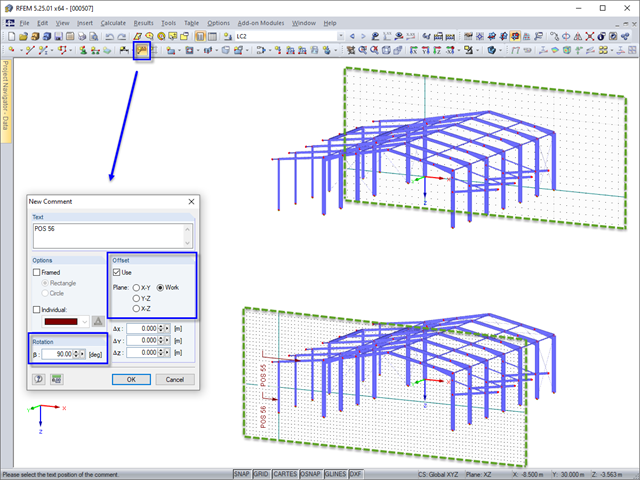
In RFEM and RSTAB, you can add a comment to model objects in the graphic. When inserting a comment, the origin of the current work plane automatically jumps temporarily to the same plane in which the comment is placed. This prevents comments from being accidentally placed very far from the object.
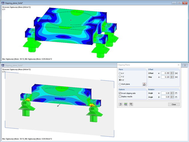
The "Clipping Plane" function allows you to define any section through the model.

The classification of cross-sections according to EN 1993-1-1 using Table 5.2 is a simple method for designing the local buckling of cross-section parts. For cross-sections of cross-section class 4, it is then necessary to determine the effective cross-section properties according to EN 1993-1-5 in order to consider the influence of local buckling in the ultimate limit state designs.
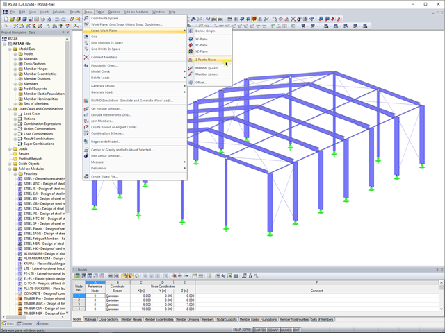
In RFEM 5 and RSTAB 8, you can now create a work plane by simply selecting three points. It is no longer necessary to create a user-defined coordinate system.
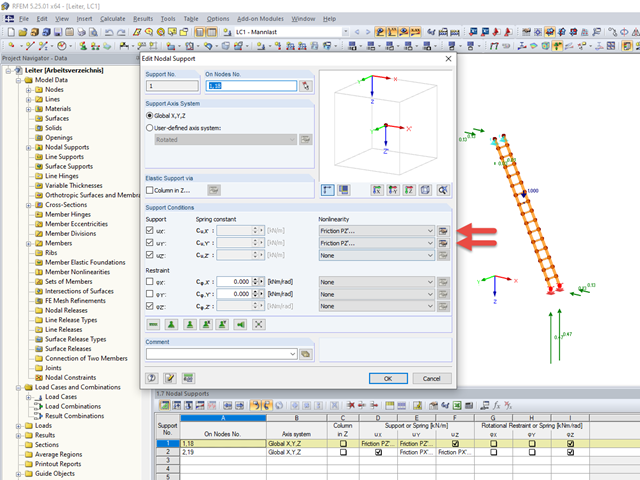
Friction plays an important role in practice. Without friction, the brakes of cars would be useless, objects on inclined planes would just slide away, and prestressed bolt connections would be impossible.

When connecting tension-loaded components with bolted connections, the cross-section reduction due to the bolt holes must be taken into account in the ultimate limit state design. This article describes how the design of the tension resistance according to DIN EN 1993‑1‑1 can be performed with the net cross-section area of the tension member in the RF‑/STEEL EC3 add-on module.

The classification of cross-sections according to EN 1993‑1‑1 and EN 1993‑1‑5 can be carried out automatically in the RF‑/STEEL EC3 add-on module. The maximum c/t ratios are specified in the standard for straight cross-section parts. There are no normative specifications for curved cross-section parts; therefore, the cross-section classification cannot be performed for these cross-section parts.
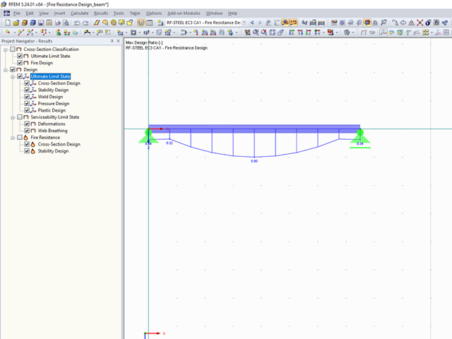
The final results of the designs of members and sets of members in the RF‑/STEEL EC3 add-on module can be displayed graphically in the work window of RFEM and RSTAB. By selecting the corresponding design case in the load case menu, the results contained in it are displayed.

When defining the effective slab width of T-beams, RFEM provides the predefined widths that are determined as 1/6 and 1/8 of the member length. A more detailed explanation on these two factors is given below.