42 Wyniki
Wyświetl wyniki:
Sortuj według:
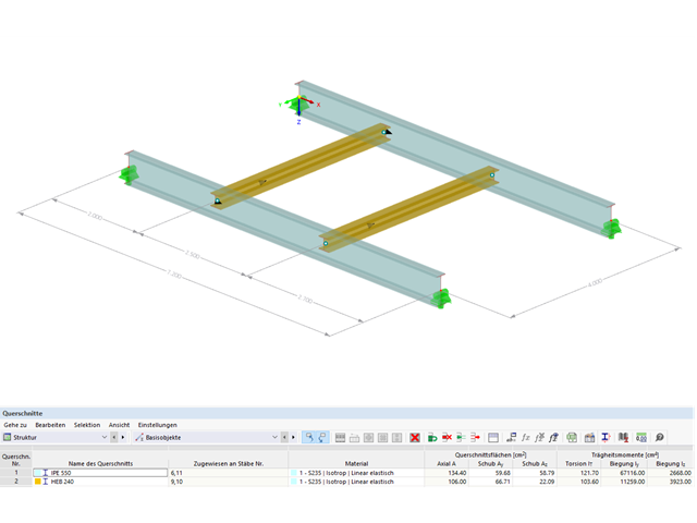
Przykład ten jest opisany w literaturze technicznej [1] jako przykład 9.5 oraz w [2] jako przykład 8.5. Dla podciągu należy przeprowadzić analizę zwichrzenia. Belka jest jednorodnym prętem konstrukcyjnym. Analizę stateczności można zatem przeprowadzić zgodnie z sekcją 6.3.2 normy DIN EN 1993-1-1. Ze względu na zginanie jednoosiowe, możliwe byłoby przeprowadzenie obliczeń również metodą ogólną według rozdz. 6.3.4. Ponadto, na wyidealizowanym modelu pręta należy zweryfikować wyznaczenie współczynnika obciążenia krytycznego w ramach w/w metody z modelem MES.

Jedną z innowacji w programie RFEM 6 jest nowy sposób projektowania połączeń stalowych. W przeciwieństwie do programu RFEM 5, w którym wymiarowanie połączeń stalowych opiera się na rozwiązaniu analitycznym, rozszerzenie Połączenia stalowe w programie RFEM 6 oferuje rozwiązanie dla połączeń stalowych w oparciu o analizę MES.

Analiza sejsmiczna w programie RFEM 6 jest możliwa przy użyciu rozszerzeń analizy modalnej i analizy spektrum odpowiedzi. Ogólna koncepcja analizy sejsmicznej w programie RFEM 6 opiera się na utworzeniu przypadku obciążenia do analizy modalnej lub analizy spektrum odpowiedzi. Grupy norm dla tych analiz są ustawiane w zakładce Normy II w oknie Dane podstawowe modelu.

Sprawdzenie stateczności dla wymiarowania prętów zastępczych zgodnie z EN 1993-1-1, AISC 360, CSA S16 i innymi normami międzynarodowymi wymaga uwzględnienia długości obliczeniowej (tj. efektywnej długości prętów). W programie RFEM 6 długość efektywną można określić ręcznie, przypisując podpory węzłowe i współczynniki długości efektywnej lub, z drugiej strony, poprzez import z analizy stateczności. Obie opcje zostaną przedstawione w tym artykule poprzez określenie efektywnej długości słupa obramowanego na rysunku 1.
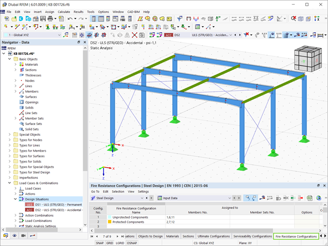
Stal ma słabe właściwości termiczne pod względem ognioodporności. Rozszerzalność termiczna dla wzrastającej temperatury jest bardzo duża w porównaniu z rozszerzalnością innych materiałów budowlanych i może powodować efekty, których nie byłoby w obliczeniach w normalnej temperaturze ze względu na utwierdzenie elementu. Wraz ze wzrostem temperatury wzrasta ciągliwość stali, a jej wytrzymałość maleje. Ponieważ stal traci 50% swojej wytrzymałości w temperaturze 600 °C, ważne jest, aby chronić elementy przed skutkami pożaru. W przypadku zabezpieczonych elementów stalowych, dzięki lepszej reakcji termicznej można wydłużyć ognioodporność.
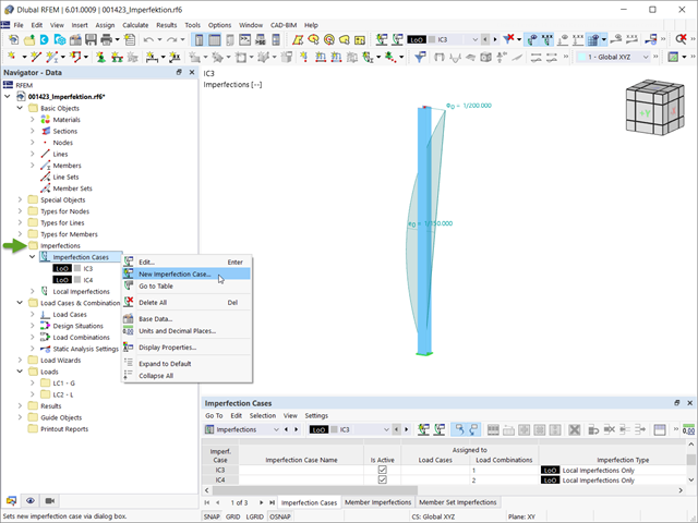
Imperfekcje w inżynierii konstrukcyjnej to odchylenia elementów konstrukcyjnych od ich idealnego kształtu, powstałe podczas produkcji. Są one często wykorzystywane w obliczeniach w celu określenia równowagi sił w elementach konstrukcyjnych w układzie odkształconym.
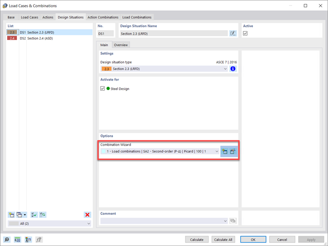
Norma dotycząca konstrukcji stalowych AISC 360-16 wymaga uwzględnienia stateczności konstrukcji jako całości oraz każdego z jej elementów. Dostępne są różne metody, w tym metoda bezpośredniego uwzględnienia w analizie, metoda długości efektywnej i metoda analizy bezpośredniej. W tym artykule podkreślono ważne wymagania rozdz. C oraz metodę bezpośredniej analizy, która zostanie uwzględniona w modelu konstrukcji stalowej wraz z zastosowaniem w programie RFEM 6.
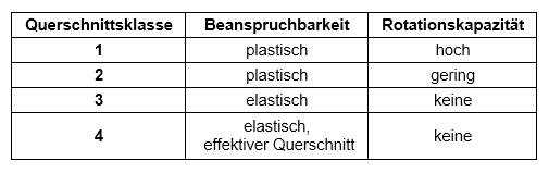
Obliczenia przekrojów zgodnie z Eurokodem 3 opierają się na klasyfikacji projektowanego przekroju według klas określonych w normie. Klasyfikacja przekrojów jest ważna, ponieważ określa granice nośności i nośności obrotowej na skutek wyboczenia lokalnego części przekroju.

Dzięki rozszerzeniu Połączenia stalowe dla RFEM 6 można tworzyć i analizować połączenia stalowe przy użyciu wydzielonego modelu ES. Modelowanie połączeń można kontrolować poprzez proste i wygodne wprowadzanie elementów. Elementy stalowego połączenia można definiować ręcznie lub przy użyciu szablonów dostępnych w bibliotece. Pierwsza metoda została opisana w poprzednim artykule z Bazy wiedzy zatytułowanym „Nowe podejście do wymiarowania połączeń stalowych w programie RFEM 6”. W tym artykule skupimy się na tej drugiej metodzie; tzn. pokaże, jak definiować komponenty połączenia stalowego przy użyciu szablonów dostępnych w bibliotece programu.

W programie RFEM 6 połączenia stalowe definiuje się jako układ elementów. W nowym rozszerzeniu Połączenia stalowe dostępne są podstawowe komponenty do uniwersalnego zastosowania (blachy, spoiny, płaszczyzny pomocnicze). Metody definiowania połączeń opisano w dwóch poprzednich artykułach w Bazie informacji: „Nowe podejście do wymiarowania połączeń stalowych w programie RFEM 6” oraz „Definiowanie elementów połączenia stalowego przy użyciu biblioteki” .

Zaletą modułu dodatkowego RFEM 6 Steel Joints jest możliwość analizy połączeń stalowych przy użyciu modelu MES, dla którego modelowanie przebiega w pełni automatycznie w tle. Elementy składowe złącza stalowego, które kontrolują modelowanie, można wprowadzić, definiując je ręcznie lub korzystając z dostępnych szablonów w bibliotece. Ta ostatnia metoda została opisana w poprzednim artykule z Bazy wiedzy zatytułowanym „Definiowanie komponentów połączenia stalowego przy użyciu biblioteki”. Definiowanie parametrów do wymiarowania połączeń stalowych jest tematem artykułu w bazie wiedzy „Projektowanie połączeń stalowych w RFEM 6”.

Analiza modalna jest punktem wyjścia do analizy dynamicznej układów konstrukcyjnych. Można ją wykorzystać do określenia wartości drgań własnych, takich jak częstotliwości drgań własnych, kształty drgań własnych, masy modalne i efektywne współczynniki masy modalnej. Wynik ten może zostać wykorzystany do obliczeń drgań oraz do dalszych analiz dynamicznych (na przykład obciążenia widmem odpowiedzi).

Analiza dynamiczna w RFEM 6 i RSTAB 9 jest podzielona na kilka rozszerzeń. Rozszerzenie Analiza modalna jest niezbędne dla wszystkich innych rozszerzeń do analizy dynamicznej, ponieważ przeprowadza analizę drgań własnych dla modeli prętów, powierzchni i brył.

W tym artykule pokazano praktyczny przykład, jak określać współczynniki obciążenia krytycznego i odpowiadające im kształty drgań w programie RFEM 6.
W tym artykule opisujemy, w jaki sposób można używać rozszerzenia Skręcanie skrępowane (7 stopni swobody) i Stateczność konstrukcji w celu uwzględnienia deplanacji przekroju jako dodatkowego stopnia swobody podczas analizy stateczności.
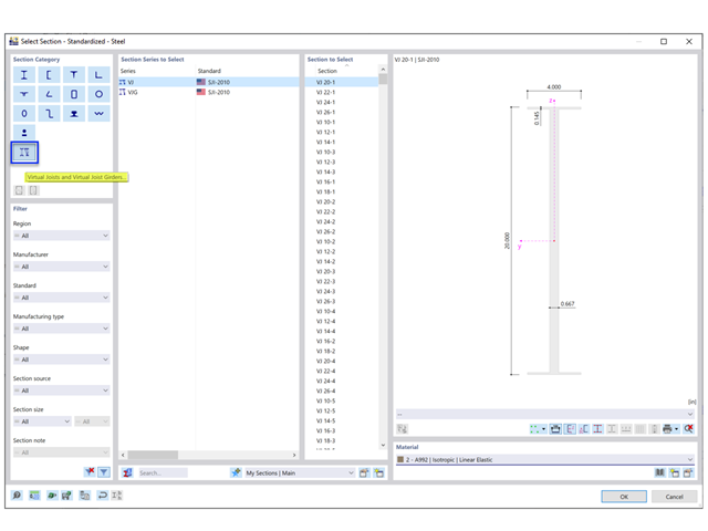
Steel Joist Institute (SJI) wcześniej opracował tabele wirtualnych belek nośnych w celu oszacowania właściwości przekroju dla belek stalowych z otwartym środnikiem. Te przekroje belek wirtualnych są scharakteryzowane jako równoważne belki o szerokich półkach, które są bardzo zbliżone do pola powierzchni pasa, efektywnego momentu bezwładności i ciężaru. Wirtualne belki nośne są również dostępne w bazie danych przekrojów w programach RFEM i RSTAB.

Wymiarowanie prętów stalowych formowanych na zimno zgodnie z AISI S100-16 jest teraz dostępne w programie RFEM 6. Design can be accessed by selecting “AISC 360” as the standard in the Steel Design add-on. “AISI S100” is then automatically selected for the cold-formed design (Image 01).
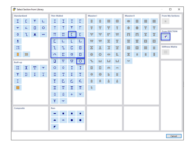
W obliczeniach konstrukcji stalowych formowanych na zimno często wymagane są niestandardowe przekroje. In RFEM 6, the custom section can be created using one of the “Thin-Walled” sections available in the library. For other sections that do not meet any of the 14 available cold-formed shapes, the sections can be created and imported from the standalone program, RSECTION. For general information on AISI steel design in RFEM 6, refer to the Knowledge Base article provided at the end of the page.
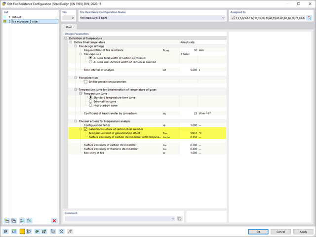
Rozszerzenie Projektowanie konstrukcji stalowych umożliwia wymiarowanie stalowych elementów konstrukcyjnych na wypadek pożaru, z zastosowaniem prostych metod obliczeniowych, zgodnie z Eurokodem 3. Temperatura elementu w chwili wykrycia może być określana automatycznie na podstawie krzywych temperatura-czas określonych w normie. Oprócz uwzględnienia okładzin przeciwpożarowych można również wziąć pod uwagę korzystne właściwości cynkowania ogniowego.
Jeżeli na górnej półce znajduje się płyta betonowa, działa ona jak podpora boczna (konstrukcja zespolona) i zapobiega problemom ze statecznością przy wyboczeniu skrętnym. Jeżeli moment zginający jest ujemny, dolna półka jest obciążona, a górna rozciągana. Jeżeli podparcie boczne nie jest wystarczające ze względu na sztywność środnika, kąt pomiędzy dolną półką a linią nacięcia środnika jest zmienny, przez co istnieje możliwość wystąpienia niestateczności wymiarowej dolnej półki.