60 Wyniki
Wyświetl wyniki:
Sortuj według:

- 002876
- Ogólne informacje
- Projektowanie konstrukcji betonowych RFEM 6
- Projektowanie konstrukcji betonowych RSTAB 9
Szczegółowe instrukcje dotyczące obliczeń są wyświetlane osobno, na podstawie obliczeń dotyczących konstrukcji.

Tabela wyników modelu budynku 'Wyniki według kondygnacji' przedstawia środek ciężkości przypadków obciążeń i kombinacji obciążeń. Oprócz obciążenia stałego uwzględniane są również obciążenia pionowe odpowiednich przypadków obciążeń i kombinacji obciążeń.
W celu wyświetlenia środka ciężkości z uwzględnieniem wybranego obciążenia można również użyć okna dialogowego 'Środek ciężkości oraz Informacje o wybranych obiektach.

W rozszerzeniu Model budynku można zdefiniować właściwości ścian usztywniających i belek-ścian dla odpowiednich rozszerzeń.

Do modelowania kondygnacji, w przypadku płyt można wykorzystać opcję "Tarcza podatna".
Zasadniczo ta opcja modelowania wybiera to samo podejście, co w przypadku modelowania kondygnacji typu "Sztywna przepona". W przeciwieństwie do sztywnej przepony, sprzężenie węzłowe nie jest przeprowadzane od środka ciężkości do każdego węzła ES. W ten sposób możliwe jest uwzględnienie elastyczności płyty.

W rozszerzeniu Projektowanie konstrukcji betonowych dla programu RFEM 6 można przeprowadzić obliczenia odporności ogniowej ścian i płyt żelbetowych zgodnie z uproszczoną metodą tabelaryczną (EN 1992-1-2, rozdział 5.4.2 oraz tabele 5.8 i 5.9).

Podczas generowania ścian usztywniających i belek-ścian można przydzielać nie tylko powierzchnie i komórki, ale także pręty.

W rozszerzeniu Projektowanie konstrukcji betonowych można zdefiniować istniejące pionowe zbrojenie na ścinanie. Jest to następnie uwzględniane przy obliczaniu wytrzymałości na przebicie.

W obliczeniach modelu budynku można pominąć otwory o określonej powierzchni. Funkcję tę można aktywować w ustawieniach globalnych kondygnacji budynku. Pojawi się komunikat ostrzegający, że otwory zostały pominięte.

- 002801
- Ogólne informacje
- Projektowanie konstrukcji betonowych RFEM 6
- Projektowanie konstrukcji betonowych RSTAB 9
Masz indywidualne przekroje słupów i ścian o różnej geometrii, które wymagają obliczenia nośności na przebicie?
Nie ma problemu. W programie RFEM 6 można przeprowadzić obliczenia na przebicie nie tylko dla przekrojów prostokątnych i okrągłych, ale także dla dowolnego kształtu przekroju.

Model budynku jest obliczany w dwóch etapach:
- Globale 3D-Berechnung des Gesamtmodells, in welchem die Decken als starre Ebene (Diaphragma) oder als Biegeplatte modelliert werden
- Lokale 2D-Berechnung der einzelnen Geschossdecken
Die Ergebnisse der Stützen und Wände aus der 3D-Berechnung und die Ergebnisse der Decken aus der 2D-Berechnung werden nach der Berechnung in einem einzigen Modell zusammengefasst. Dadurch muss zwischen dem 3D-Modell und der einzelnen 2D-Modellen der Decken nicht gewechselt werden. Der Anwender arbeitet nur mit einem Model, spart wertvolle Zeit und vermeidet eventuelle Fehler beim händischen Datenaustausch zwischen dem 3D-Modell und der einzelnen 2D-Decken-Modelle.
Die vertikalen Flächen im Modell können vom Nutzer in Schubwände (Shear Walls) und Öffnungsstürze (Sprandels) geteilt werden. Aus diesen Wandobjekten erzeugt das Programm automatisch interne Ergebnisstäbe, so dass diese dann nach der gewünschten Norm im Add-On Betonbemessung für RFEM 6 als Stäbe bemessen werden können.

Ściany usztywniające i belki-ściany z modelu budynku są dostępne jako niezależne obiekty w rozszerzeniach. W ten sposób możliwe jest szybsze filtrowanie obiektów w wynikach oraz tworzenie lepszej dokumentacji w raporcie.

Za pomocą generatora kondygnacji w rozszerzeniu Model budynku można automatycznie tworzyć kondygnacje budynku w zależności od topologii modelu.

W przypadku analizy spektrum odpowiedzi modeli budynków można wyświetlić współczynniki wrażliwości dla kierunków poziomych według kondygnacji.
Dzięki tym kluczowym wartościom można zinterpretować wrażliwość na efekty stateczności.

- 002720
- Ogólne informacje
- Analiza stateczności konstrukcji RFEM 6
- Analiza stateczności konstrukcji RSTAB 9
Stosując modalny współczynnik istotności (MRF) można ocenić, w jakim stopniu poszczególne elementy konstrukcyjne przyczyniają się do powstania rzeczywistego kształtu wyboczenia. Obliczenia opierają się na energii względnego odkształcenia sprężystego każdego pojedynczego pręta.
Dzięki MRF można rozróżnić lokalne i globalne kształty wyboczenia. Jeżeli kilka prętów ma znaczny MRF (np. > 20%), bardzo prawdopodobna jest niestateczność całej konstrukcji lub jej części. Jeżeli jednak suma wszystkich MRF dla kształtu drgań wynosi około 100%, należy spodziewać się lokalnego problemu ze statecznością (np. wyboczenia pojedynczego pręta).
Ponadto MRF może być wykorzystany do określenia obciążeń krytycznych i równoważnych długości wyboczeniowych poszczególnych prętów (np. do analizy stateczności). Kształty wyboczenia, dla których dany pręt ma małe wartości MRF (np. <20%), mogą zostać w tym kontekście pominięte.
MRF jest wyświetlany według kształtów wyboczenia w tabeli wyników w sekcji Analiza stateczności --> Wyniki według prętów --> Długości efektywne i obciążenia krytyczne.

- 002691
- Ogólne informacje
- Projektowanie konstrukcji betonowych RFEM 6
- Projektowanie konstrukcji betonowych RSTAB 9
W rozszerzeniu Projektowanie konstrukcji betonowych można przeprowadzić uproszczone obliczenia odporności ogniowej słupów (Rozdział 5.3.2) i belek (Rozdział 5.6), zgodnie z EN 1992-1-2.
W przypadku uproszczonych obliczeń odporności ogniowej dostępne są następujące metody weryfikacji:
- Słupy: Minimalne wymiary przekroju prostokątnego i okrągłego wg tabeli 5.2a oraz równania 5.7 do obliczania czasu ekspozycji pożarowej
- Belki: Minimalne wymiary i odległości między środkami zgodnie z Tabelą 5.5 i Tabelą 5.6
Siły wewnętrzne do obliczeń odporności ogniowej można wyznaczyć przy użyciu dwóch metod.
- 1: W tym przypadku siły wewnętrzne z wyjątkowej sytuacji obliczeniowej są bezpośrednio uwzględniane w obliczeniach.
- 2: Siły wewnętrzne z obliczeń w temperaturze normalnej są redukowane za pomocą współczynnika Eta,fi (ηfi) i są następnie wykorzystywane do obliczeń odporności ogniowej.
Ponadto istnieje możliwość modyfikacji rozstawu osi zgodnie z równ. 5.5.

Rozszerzenie Projektowanie konstrukcji betonowych umożliwia wymiarowanie prętów i powierzchni ze względu na zmęczenie zgodnie z EN 1992-1-1, rozdział 6.8.
W przypadku obliczeń zmęczenia można opcjonalnie wybrać dwie metody lub poziomy obliczeniowe w konfiguracjach obliczeniowych:
- Poziom obliczeniowy 1: Obliczenia uproszczone wg. do 6.8.6 i 6.8.7(2) Kryterium uproszczone jest stosowane dla częstych kombinacji oddziaływań zgodnie z EN 1992-1-1, rozdział 6.8.6 (2) oraz EN 1990, równ. (6.15b) wraz z obciążeniami od ruchu drogowego w stanie użytkowalności. Dla stali zbrojeniowej sprawdzany jest maksymalny zakres naprężeń zgodnie z 6.8.6. Naprężenie ściskające w betonie jest określane za pomocą górnego i dolnego dopuszczalnego naprężenia zgodnie z 6.8.7(2).
- Poziom analizy 2: Obliczanie równoważnego naprężenia niszczącego zgodnie z 6.8.5 i 6.8.7(1) (uproszczone obliczenia na zmęczenie): Obliczenia z wykorzystaniem zakresów równoważnych naprężeń niszczących są przeprowadzane dla kombinacji zmęczeniowych, zgodnie z EN 1992-1-1, rozdział 6.8.3, równ. (6.69) o specyficznie zdefiniowanym oddziaływaniu cyklicznym Qfat .

W rozszerzeniu Projektowanie konstrukcji betonowych można przeprowadzać obliczenia sejsmiczne dla prętów żelbetowych zgodnie z EC 8. Są to między innymi następujące funkcje:
- Konfiguracje obliczeń sejsmicznych
- Rozróżnianie klas ciągliwości DCL, DCM, DCH
- Możliwość przeniesienia współczynnika odpowiedzi z analizy dynamicznej
- Sprawdzenie wartości granicznej współczynnika odpowiedzi
- Weryfikacja nośności dla "Wytrzymały słup - słaba belka"
- Uszczegółowienie i reguły szczególne dla współczynnika ciągliwości krzywizny
- Uszczegółowienie i reguły szczególne dla ciągliwości lokalnej

Wprowadzenie typu obciążenia Woda stojąca umożliwia symulację oddziaływań deszczu na powierzchnie wielokrotnie zakrzywione, z uwzględnieniem przemieszczeń według analizy dużych odkształceń.
Ten numeryczny proces analizy deszczowej analizuje przypisaną geometrię powierzchni i określa, które składowe wody deszczowej spływają, a które gromadzą się w postaci kałuży (kieszeni wodnych) na powierzchni. Rozmiar kałuży powoduje wówczas odpowiednie obciążenie pionowe do analizy statyczno-wytrzymałościowej.
Funkcja ta jest przeznaczona do analizy w przybliżeniu poziomych geometrii dachów membranowych pod obciążeniem deszczem.
Przejdź do filmu
W przypadku elementów w modelach budynków dostępnych jest kilka narzędzi do modelowania:
- Linia pionowa
- Słup
- Ściana
- Belka
- Strop prostokątny
- Płyta wielokątna
- Prostokątny otwór w stropie
- Wielokątny otwór w stropie
Ta funkcja umożliwia definicję elementów na płaszczyźnie podłoża (na przykład z warstwą tła) z powiązanym tworzeniem wielu elementów w przestrzeni.

Teraz w rozszerzeniu Projektowanie konstrukcji betonowych można wymiarować elementy wykonane z betonu zbrojonego włóknami zgodnie z wytyczną "DAfStb Steel Fiber-Reinforced Concrete".
Ta opcja jest dostępna dla obliczeń zgodnie z EN 1992-1-1. Obliczenia zgodnie z wytyczną DAfStb są przeprowadzane po przypisaniu betonu typu "Fibrobeton" do elementu konstrukcyjnego z betonu zbrojonego.
Przejdź do filmu
W zakładce "Zbrojenie na ścinanie" można wybrać opcję "Powiązania krzyżowe na wolnych prętach zbrojeniowych z aktywnym wyborem w oknie graficznym". Pozwala to na umieszczenie dodatkowych powiązań krzyżowych na wolnych prętach zbrojenia podłużnego.
Pozycję więzów krzyżowych można aktywować lub dezaktywować w infografice. Powiązania krzyżowe są uwzględniane podczas kontroli stanu granicznego nośności i obliczeń konstrukcji. Są one dostępne dla obliczeń zgodnie z EN 1992-1-1.
Przejdź do filmu
Korzystając z kondygnacji typu "Tylko przenoszenie obciążenia", można uwzględnić w rozszerzeniu Model budynku stropy bez wpływu sztywności do i z płaszczyzny. Ten typ elementu zbiera obciążenia na stropie i przenosi je na elementy nośne modelu 3D. Daje to możliwość symulacji w modelu 3D elementów drugorzędnych, takich jak np. ruszt i inne podobne elementy rozkładu obciążenia, bez dalszych efektów.

W rozszerzeniu Projektowanie konstrukcji betonowych można wymiarować dowolny przekrój RSECTION. Otulinę betonową, zbrojenie na ścinanie i zbrojenie podłużne definiuje się bezpośrednio w RSECTION.
Po zaimportowaniu przekroju ze zbrojeniem RSECTION do programu RFEM 6, można go również wykorzystać do obliczeń w rozszerzeniu Projektowanie konstrukcji betonowych.
Przejdź do filmu
- 002557
- Ogólne informacje
- Projektowanie konstrukcji betonowych RFEM 6
- Projektowanie konstrukcji betonowych RSTAB 9
Skorzystaj i oszczędzaj czas! Ta funkcja umożliwia jednoczesne definiowanie lub edycję zbrojenia dla kilku prętów lub zbiorów prętów.
Przejdź do filmu
Istniejące zbrojenie powierzchniowe można automatycznie zaprojektować tak, aby pokryć wymagane zbrojenie. Można wybrać, czy automatycznie ma być definiowana średnica zbrojenia, czy też rozstaw prętów.
Przejdź do filmu
Aktywowałeś rozszerzenie Model budynku ? Bardzo dobrze! Możesz wyświetlić środek sztywności w tabeli i w formie graficznej. Użyj go na przykład do analizy dynamicznej.

- 002469
- Ogólne informacje
- Projektowanie konstrukcji betonowych RFEM 6
- Projektowanie konstrukcji betonowych RSTAB 9
Pracujesz z elementami konstrukcyjnymi składającymi się z płyt? W takim przypadku należy przeprowadzić obliczenia na ścinanie z uwzględnieniem wymagań obliczania przebicia, na przykład zgodnie z 6.4, EN 1992-1-1. Oprócz płyt stropowych można w ten sposób wymiarować również płyty fundamentowe.
W konfiguracji stanu granicznego nośności dla wymiarowania betonu można zdefiniować parametry obliczeń przebicia dla wybranych węzłów.
.png?mw=640&hash=342149908caead326e60e26a2b5d05f7f46825cb)
Czy znasz już model materiałowy Tsai-Wu? Łączy w sobie właściwości plastyczne i ortotropowe, co pozwala na specjalne modelowanie materiałów o charakterystyce anizotropowej, takich jak tworzywa sztuczne wzmocnione włóknami czy drewno.
Podczas uplastycznienia materiału naprężenia pozostają stałe. Zachodzi redystrybucja w zależności od sztywności występującej w poszczególnych kierunkach. Obszar sprężysty odpowiada powierzchni ortotropowej | Liniowy sprężysty model materiałowy (bryły). Dla strefy plastycznej ma zastosowanie następujące kryterium plastyczności według Tsai-Wu:
Wszystkie wytrzymałości są zdefiniowane jako dodatnie. Kryterium naprężeń można sobie wyobrazić jako powierzchnię eliptyczną w sześciowymiarowej przestrzeni naprężeń. Jeżeli jedna z trzech składowych naprężenia zostanie przyłożona jako stała wartość, powierzchnię tę można rzutować na trójwymiarową przestrzeń naprężeń.
Jeżeli wartość fy (σ), zgodnie z równaniem Tsai-Wu, płaski warunek naprężenia, jest mniejsza niż 1, naprężenia znajdują się w strefie sprężystej. Powierzchnia plastyczna zostaje osiągnięta, gdy fy (σ) = 1; wartości większe niż 1 nie są dozwolone. Zachowanie modelu jest idealnie plastyczne, co oznacza, że nie występuje usztywnienie.

Masz pytania dotyczące programu? W przeciwieństwie do innych modeli materiałowych, wykres naprężenie-odkształcenie dla tego modelu materiałowego nie jest antymetryczny względem początku. Ten model materiałowy można wykorzystać na przykład do symulacji zachowania betonu zbrojonego włóknami stalowymi. Ausführliche Hinweise zum Modellieren von Stahlfaserbeton finden Sie im Fachbeitrag: Określanie właściwości materiałowych betonu zbrojonego włóknami stalowymi i ich zastosowanie w RFEM
W tym modelu materiału sztywność izotropowa jest redukowana za pomocą skalarnego parametru uszkodzenia. Ten parametr uszkodzenia wyznaczany jest z krzywej naprężeń określonej na wykresie. Nie uwzględnia się kierunku naprężeń głównych. Zamiast tego uszkodzenie występuje w kierunku odkształcenia zastępczego, które obejmuje również trzeci kierunek prostopadły do płaszczyzny. Obszary rozciągania i ściskania tensora naprężeń są traktowane oddzielnie. Dabei gelten jeweils unterschiedliche Schädigungsparameter.
"Wielkość elementu odniesienia" określa, w jaki sposób odkształcenie w obszarze rys jest skalowane do długości elementu. Przy domyślnej wartości zero skalowanie nie jest wykonywane. Pozwala to na realistyczne modelowanie zachowania materiałowego betonu zbrojonego włóknami stalowymi.
Theoretische Hintergründe zum Materialmodell 'Isotrop Beschädigung' können Sie im Fachbeitrag nachlesen: KB 001461 │ Uszkodzenie nieliniowych modeli materiałowych .
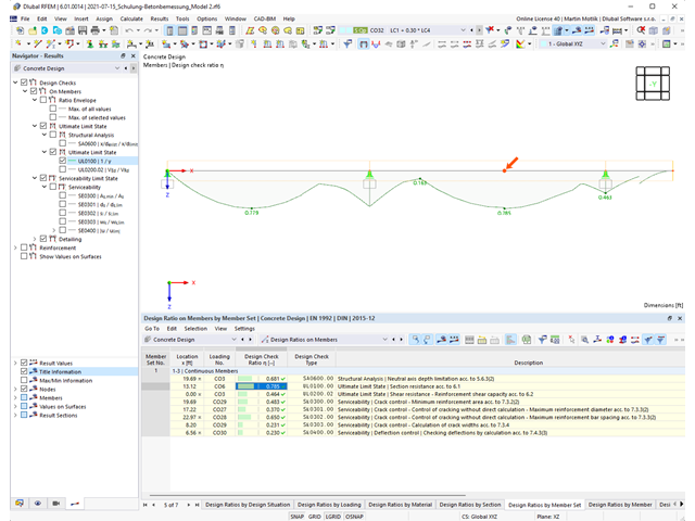
Program do analizy statyczno-wytrzymałościowej zapewnia przejrzysty przegląd wszystkich przeprowadzonych kontroli obliczeń dla określonej normy obliczeniowej. Dla każdego warunku projektowego należy określić kryterium obliczeniowe. Oprócz sprawdzania stanu granicznego nośności i użytkowalności program sprawdza zasady projektowania określone w normie. Dla każdej kontroli obliczeń są określone szczegóły obliczeń, w tym wartości początkowe, wyniki pośrednie i wyniki końcowe. Proces obliczeń wraz z zastosowanymi wzorami, standardowymi źródłami i wynikami szczegółowo przedstawiony jest w oknie informacyjnym w szczegółach obliczeń.