39 Wyniki
Wyświetl wyniki:
Sortuj według:
Obciążenia wiatrem mogą być automatycznie generowane jako obciążenia prętów lub obciążenia powierzchniowe na następujących elementach konstrukcyjnych (opcjonalnie z ciśnieniem wewnętrznym w przypadku budynków otwartych):
- Ściany pionowe
- Dachy płaskie
- Dachy jednospadowe
- Dachy dwuspadowe/korytowe
- Ściany pionowe wraz z dachem
Dostępne są poniższe normy:
-
 EN 1991-1-3 (wraz z załącznikami krajowymi)
 -
 DIN 1055-4
 -
 CTE DB-SE-AE
 -
 ASCE/SEI 7-16
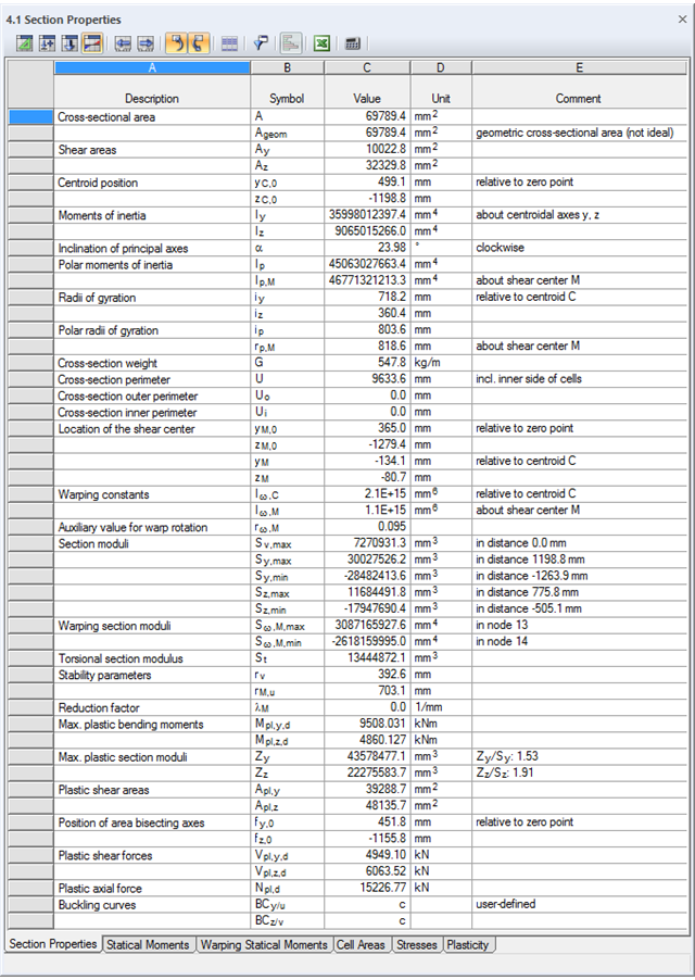
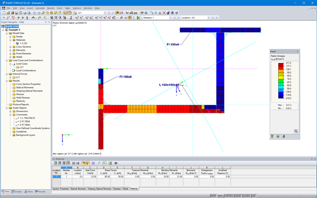
SHAPE-THIN określa charakterystyki przekroju i naprężenia dla przekrojów otwartych, zamkniętych, połączonych i niepołączonych.
- parametry przekroju
- Pole przekroju A
- Pole ścinane Ay, Az, Au i Av
- Położenie środka ciężkości yS, zS
- momenty pola 2 stopnie Iy, Iz, Iyz, Iu, Iv, Ip, Ip,M
- Promienie bezwładności iy, iz, iyz, iu, iv, ip, ip,M
- Nachylenie osi głównych α
- Ciężar przekroju G
- Średnica przekroju U
- momenty bezwładności przy skręcaniu stopnieIT , IT , IT,St.Venant, IT,Bredt, IT,s
- Położenie środka ścinania yM, zM
- Stałe deplanacji Iω,S, Iω,M or Iω,D dla utwierdzenia bocznego
- Max/min moduły przekroju Sy, Sz, Su, Sv, Sω,M z położeniami
- Promienie przekroju ru, rv, rM,u, rM,v
- Współczynnik redukcyjny λM
- Plastyczne charakterystyki przekroju
- Siła osiowa Npl,d
- Siły tnące Vpl,y,d, Vpl,z,d, Vpl,u,d, Vpl,v,d
- Momenty zginające Mpl,y,d, Mpl,z,d, Mpl,u,d, Mpl,v,d
- Moduły przekroju Zy, Zz, Zu, Zv
- Pola ścinania Apl,y, Apl,z, Apl,u, Apl,v
- Położenie osi powierzchni fu, fv,
- Wyświetlanie elipsy bezwładności
- Momenty statyczne pola Qu, Qv, Qy, Qz z położeniem maksimum i określeniem przebiegu ścinania
- Współrzędne wycinkowe ωM
- momenty bezwładności (wycinkowe powierzchnie) Sω,M
- Pola komórek Am zamkniętych przekrojów
- Naprężenia normalne σx wywołane siłą osiową, momentem zginającym i bimomentem deplanacji
- Naprężenia styczne τ od sił tnących oraz pierwotnych i drugorzędnych momentów skręcających
- Naprężenia zastępcze σv ze współczynnikiem dla naprężeń ścinających, który można dostosować do własnych potrzeb
- Stopnie wykorzystania odniesione do naprężeń granicznych
- Naprężenia dla krawędzi lub osi elementu
- Naprężenia w spoinach pachwinowych
- Charakterystyki przekrojów niepołączonych (rdzeń budynku wysokościowego, przekroje złożone)
- Siły tnące wywołane zginaniem i skręcaniem
- Obliczanie nośności plastycznej z określeniem współczynnika zwiększającego αpl
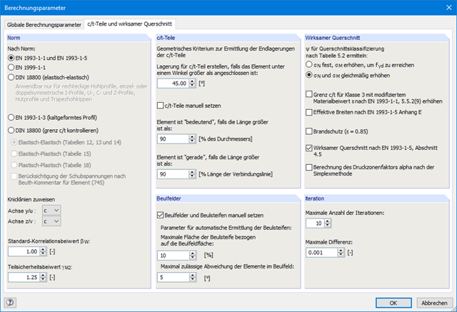
- Sprawdzenie stosunków c/t według metody el-el, el-pl lub pl-pl wg DIN 18800
Obciążenia wiatrem mogą być automatycznie generowane jako obciążenia prętów na następujących elementach konstrukcyjnych (opcjonalnie z ciśnieniem wewnętrznym w przypadku budynków otwartych):
- Ściany pionowe
- Dachy płaskie
- Dachy jednospadowe
- Dachy dwuspadowe/korytowe
- Ściany pionowe wraz z dachem
Dostępne są poniższe normy:
-
EN 1991-1-3 (wraz z załącznikami krajowymi)
-
DIN 1055-4
-
CTE DB-SE-AE
-
ASCE/SEI 7-16
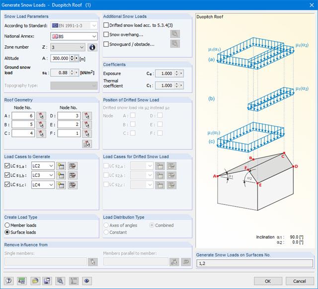
Generator obciążenia śniegiem może generować obciążenia śniegiem jako obciążenia prętowe lub obciążenia powierzchniowe.
Dodatkowe obciążenia śniegiem takie jak obciążenia śniegiem naniesionym, nasypem śnieżnym i barierkami przeciwśniegowymi mogą zostać również uwzględnione.
Dostępne są poniższe normy:
-
EN 1991-1-3 (wraz z załącznikami krajowymi)
-
DIN 1055-5
-
CTE DB-SE-AE
-
ASCE/SEI 7-16
Wszystkie wyniki mogą być wyświetlane i analizowane w postaci numerycznej i graficznej. W przypadku wizualizacji wyników, narzędzia wyboru pozwalają na ich szczegółową ocenę.
Protokół wydruku spełnia wysokie standardy Produkt | RFEM 6 und des Produkt | RSTAB 9 . Modyfikacje przekroju aktualizowane są automatycznie.
SHAPE-THIN określa wszystkie odpowiednie charakterystyki przekroju, wraz z plastycznymi siłami granicznymi i momentami. Nakładające się powierzchnie są uwzględniane w sposób realistyczny. Dla przekrojów utworzonych z różnych materiałów, SHAPE-THIN określa idealne charakterystyki przekroju w odniesieniu do materiału referencyjnego.
Oprócz analizy naprężeń w stanie sprężystym, można prowadzić również obliczenia w stanie plastycznym, zawierające interakcję sił wewnętrznych dla różnorodnych kształtów przekroju. Obliczenia interakcji plastycznej prowadzane są według metody Simplex. Podczas analizy naprężeń można wybrać różne teorie (Tresca lub von Mises).
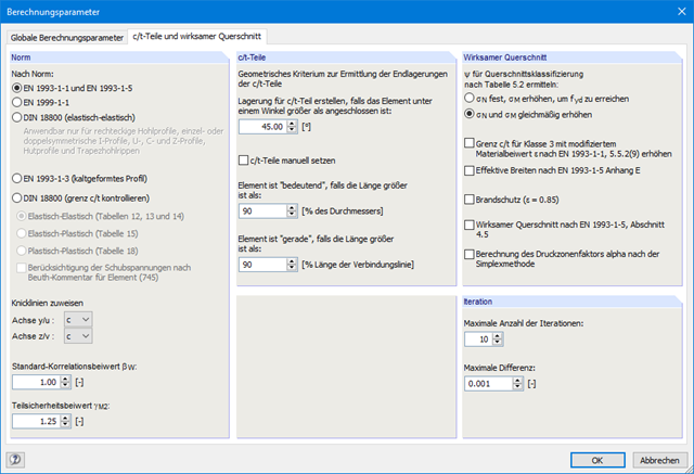
SHAPE-THIN przeprowadza klasyfikację przekroju zgodnie z EN 1993-1-1 i EN 1999-1-1. W przypadku przekrojów stalowych o przekroju 4, program określa szerokości efektywne dla płyt usztywnionych lub nieusztywnionych, zgodnie z EN 1993-1-1 i EN 1993-1-5. W przypadku przekrojów aluminiowych o przekroju klasy 4, program oblicza grubości efektywne zgodnie z EN 1999-1-1.
Opcjonalnie SHAPE-THIN sprawdza wartości graniczne c/t zgodnie z metodami obliczeniowymi el-el, el-pl lub pl-pl zgodnie z DIN 18800. Przekrój jest klasyfikowany według danej kombinacji sił wewnętrznych.
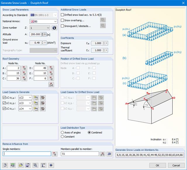
Obciążenia śniegiem mogą być generowane jako obciążenia prętów na dachach płaskich / jednospadowych i dachach dwuspadowych.
Dodatkowe obciążenia śniegiem takie jak obciążenia śniegiem naniesionym, nasypem śnieżnym i barierkami przeciwśniegowymi mogą zostać również uwzględnione.
Dostępne są poniższe normy:
-
EN 1991-1-3 (wraz z załącznikami krajowymi)
-
DIN 1055-5
-
CTE DB-SE-AE
-
ASCE/SEI 7-16

Wymiarowanie prętów stalowych formowanych na zimno zgodnie z AISI S100-16/CSA S136-16 jest dostępne w RFEM 6. Dostęp do obliczeń można uzyskać, wybierając normy „AISC 360” lub „CSA S16” w rozszerzeniu Projektowanie konstrukcji stalowych. Następnie dla obliczeń elementów formowanych na zimno automatycznie wybierane jest „AISI S100” lub „CSA S136”.
Do obliczania sprężystego obciążenia wyboczeniowego pręta program RFEM stosuje metodę DSM. Bezpośrednia metoda wytrzymałości oferuje dwa typy rozwiązań, numeryczne (metoda pasm skończonych) i analityczne (specyfikacja). Krzywą charakterystyczną (sygnaturę) FSM i kształty wyboczenia można wyświetlić w oknie dialogowym Przekroje.
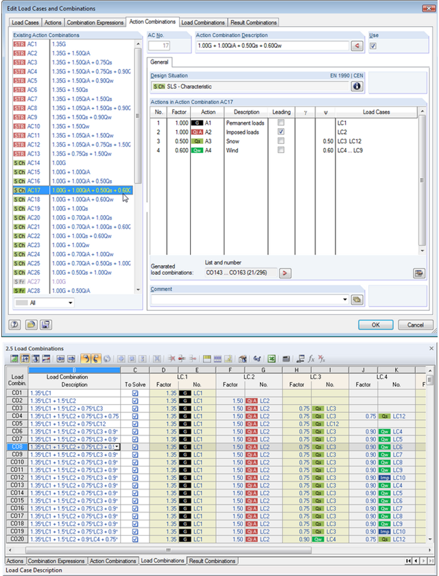
W ten sposób można wykorzystać wszystkie opcje dostępne w oknie dialogowym 'Edytować przypadki obciążeń i kombinacje', aby ułatwić sobie pracę. Po wybraniu odpowiednich reguł kombinacji można tutaj automatycznie tworzyć kombinacje obciążeń i wyników. W tym przejrzystym oknie dialogowym można np. kopiować, dodawać lub przenumerować przypadki obciążeń.
Dodatkowo należy sprawdzić przypadki i kombinacje obciążeń w tabelach 2.1 - 2.6.
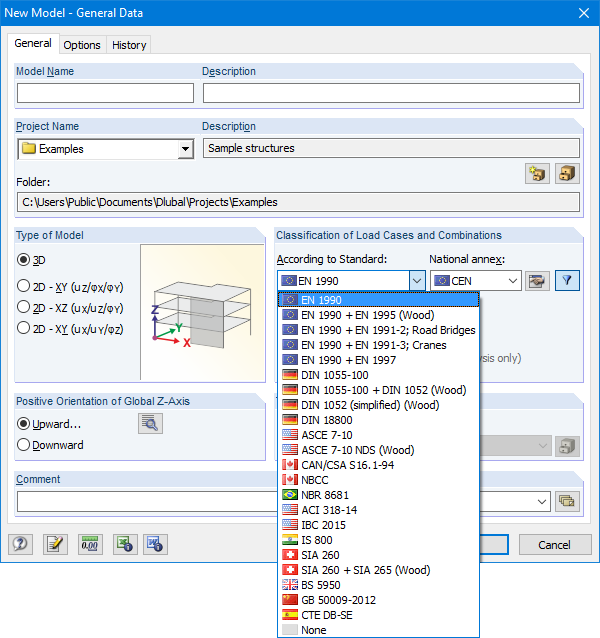
Okno dialogowe Dane podstawowe zawiera szeroką gamę norm oraz opcję automatycznego tworzenia kombinacji. Dostępne są poniższe normy:
-
EN 1990:2002
-
EN 1990 + EN 1995:2004 (Drewno)
-
EN 1990 + EN 1991-2; Mosty drogowe
-
EN 1990 + EN 1991-3; Dźwigi
-
EN 1990 + EN 1997
-
wg DIN 1055-100:2001-03
-
DIN 1055-100 + DIN 1052:2004-08 (drewno)
-
DIN 1055-100 + DIN 18008 (Glass)
-
DIN 1052 (uproszczony) (drewno)
-
DIN 18800:1990
-
ASCE 7-10
-
ASCE 7-10 NDS (Drewno)
-
ACI 318-14
-
IBC 2015
-
 CAN/CSA S 16.1-94:1994
 -
NBCC: 2005
-
 NBR 8681
 -
 IS 800:2007
 -
 SIA 260:2003
 -
SIA 260 + SIA 265:2003 (drewno)
-
 BS 5950-1:2000
 -
 GB 50009-2012
 -
CTE DB-SE
W przypadku norm europejskich (EC) dostępne są następujące załączniki krajowe:
-
DIN EN 1990/NA:2009-05 (Niemcy)
-
 NBN EN 1990 - ANB: 2005 (Belgia)
 -
 BDS EN 1990:2003/NA:2008 (Bułgaria)
 -
 DK EN 1990/NA:2007-07 (Dania)
 -
 SFS EN 1990/NA:2005 (Finlandia)
 -
 NF EN 1990/NA:2005/12 (Francja)
 -
 ELOT EN 1990:2009 (Grecja)
 -
 UNI EN 1990/NA:2007-07 (Włochy)
 -
 IS EN 1990:2002 + NA:2010 (Irlandia)
 -
 LVS EN 1990:2003/NA:2010 (Łotwa)
 -
 LST EN 1990/NA:2010-11 (Litwa)
 -
 LU EN 1990/NA:2011-09 (Luksemburg)
 -
 MS EN 1990:2010 (Malezja)
 -
 NEN EN 1990/NA:2006 (Holandia)
 - NS EN 1990/NA:2008 (Norwegia)
-
 ÖNORM EN 1990:2007-02 (Austria)
 -
 NP EN 1990:2009 (Portugalia)
 -
 PN EN 1990/NA:2004 (Polska)
 -
 SR EN 1990/NA:2006-10 (Rumunia)
 -
 SIST EN 1990: 2004/A1:2005 (Słowenia)
 -
 SS EN 1990:2008 (Singapur)
 -
 SS EN 1990/BFS 2010:28 (Szwecja)
 -
 STN EN 1990/NA:2009-08 (Słowacja)
 -
UNE EN 1990 2003 (Hiszpania)
-
 CSN EN 1990/NA:2004-03 (Republika Czeska)
 -
BS EN 1990/NA:2004-12 (Wielka Brytania)
-
 TKP EN 1990/NA:2011 (Białoruś)
 -
 CYS EN 1990:2002 (Cypr)
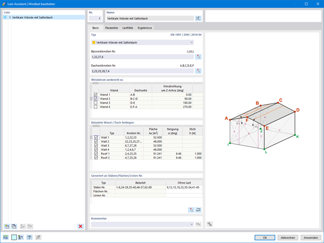
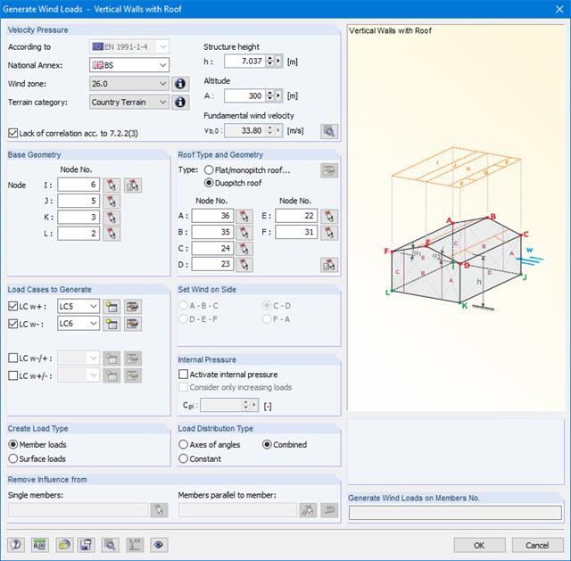
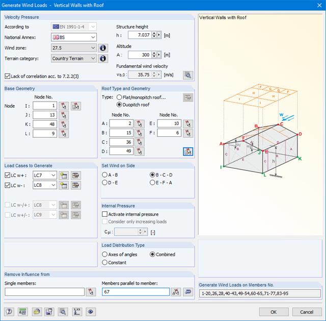
Obciążenia wiatrem również nie stanowią problemu w obliczeniach. Obciążenia wiatrem mogą być generowane automatycznie jako obciążenia prętowe lub obciążenia powierzchniowe (RFEM) na następujących elementach konstrukcyjnych:
- Ściany pionowe
- Dachy płaskie
- Dachy jednospadowe
- Dachy dwuspadowe/korytowe
- Ściany pionowe z dachem dwuspadowym
- Ściany pionowe z dachem płaskim/jednospadowym
Dostępne są następujące normy:
-
EN 1991-1-4 (wraz z załącznikami krajowymi)
-
ASCE 7
-
NBC
-
CTE DB-SE-AE
-
GB 50009

- 002462
- Ogólne informacje
- Projektowanie konstrukcji aluminiowych RFEM 6
- Projektowanie konstrukcji aluminiowych RSTAB 9
Czy do określenia współczynnika obciążenia krytycznego w ramach analizy stateczności użyto dodatkowego solwera wewnętrznych wartości własnych? W takim przypadku można następnie wyświetlić kształt wzorca projektowanego obiektu.

- 002457
- Ogólne informacje
- Projektowanie konstrukcji aluminiowych RFEM 6
- Projektowanie konstrukcji aluminiowych RSTAB 9
Rozszerzenie Projektowanie konstrukcji aluminiowych oferuje dodatkowe opcje. W tym miejscu można również obliczać przekroje ogólne, które nie są wstępnie zdefiniowane w bibliotece przekrojów. Na przykład, utwórz przekrój w programie RSECTION, a następnie zaimportuj go do RFEM/RSTAB. W zależności od zastosowanej normy projektowej dostępne są różne formaty obliczeń. Obejmuje to na przykład równoważną analizę naprężeń.
Ist zudem eine Lizenz für RSECTION und „Effektive Querschnitte“ vorhanden, so können Sie die Nachweise auch unter Berücksichtigung der effektiven Querschnittswerte nach EN 1999-1-1 führen.
SHAPE-THIN posiada obszerną bibliotekę przekrojów walcowanych i parametryzowanych. Mogą one być łączone lub uzupełniane o nowe elementy. Możliwe jest zamodelowanie przekroju składającego się z różnych materiałów.
Narzędzia i funkcje graficzne umożliwiają modelowanie złożonych kształtów przekrojów w sposób typowy dla programów CAD. W oknie graficznym można wprowadzić elementy punktowe, spoiny pachwinowe, łuki, sparametryzowane przekroje prostokątne i okrągłe, elipsy, łuki eliptyczne, parabole, hiperbole, splajn oraz NURBS. Alternatywnie można zaimportować plik DXF, który stanowi podstawę do dalszego modelowania. Podczas modelowania można użyć także linii pomocniczych.
Ponadto, sparametryzowane wprowadzanie danych umożliwia wprowadzanie danych modelu i obciążeń w określony sposób, tak aby były one zależne od określonych zmiennych.
Elementy można graficznie podzielić lub przydzielić do innych obiektów. SHAPE-THIN automatycznie dzieli elementy i zapewnia nieprzerwany przepływ ścinający poprzez wprowadzenie elementów zerowych. W przypadku elementów zerowych można zdefiniować określoną grubość, aby kontrolować przenoszenie ścinania.

- 002142
- Wyniki
- Projektowanie konstrukcji aluminiowych RFEM 6
- Projektowanie konstrukcji aluminiowych RSTAB 9
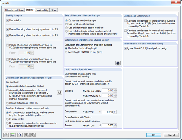
- Analiza stateczności dla wyboczenia giętnego, wyboczenia skrętnego i wyboczenia giętno-skrętnego przy ściskaniu
- Analiza zwichrzenia elementów poddanych obciążeniu momentem
- Import długości efektywnych z obliczeń przy użyciu rozszerzenia Stateczność konstrukcji
- Graficzne wprowadzanie i kontrola zdefiniowanych podpór węzłowych oraz długości efektywnych w celu analizy stateczności
- W zależności od normy istnieje wybór między wprowadzaniem wartości Mcr przez użytkownika, metodą analityczną z normy lub wykorzystaniem wewnętrznego solwera wartości własnych
- Uwzględnienie panelu usztywniającego i ograniczenia obrotu podczas korzystania z solwera wartości własnych
- Graficzne przedstawienie postaci własnej w przypadku zastosowania solwera wartości własnych
- Analiza stateczności elementów konstrukcyjnych ze ściskaniem i naprężeniem zginającym, w zależności od normy obliczeniowej
- Przejrzyste obliczanie wszystkich niezbędnych współczynników, takich jak współczynniki interakcji
- Alternatywne uwzględnienie wszystkich wpływów dla analizy stateczności podczas określania sił wewnętrznych w programie RFEM/RSTAB (analiza drugiego rzędu, imperfekcje, redukcja sztywności, ewentualnie w połączeniu z rozszerzeniem Skręcanie skrępowane (7 stopni swobody))
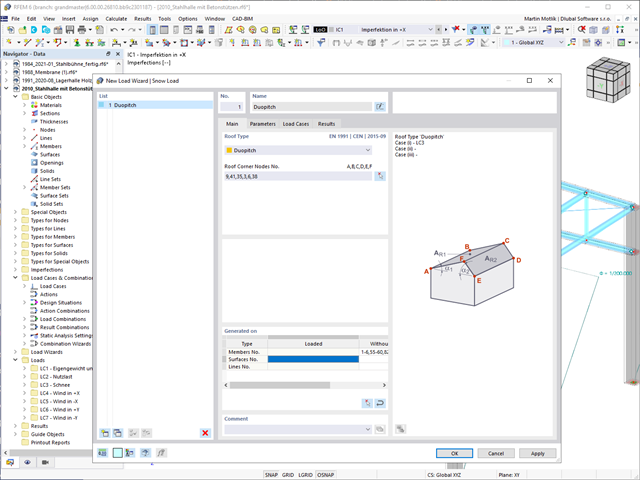
Czy Twoje konstrukcje również muszą wytrzymać opady śniegu? Za pomocą Kreatora obciążeń śniegiem można generować obciążenia śniegiem jako obciążenia prętowe lub powierzchniowe.
Dostępne są poniższe normy:
-
EN 1991-1-3 (wraz z załącznikami krajowymi)
-
ASCE 7
-
NBC
-
SIA 261
-
CTE DB-SE-AE
-
GB 50009
-
IS 875
- Modelowanie przekroju za pomocą elementów, profili, łuków i elementów punktowych
- Biblioteka właściwości materiałów, granic plastyczności i naprężeń granicznych, którą użytkownik może rozbudowywać
- Właściwości przekrojów otwartych, zamkniętych i niepołączonych
- Efektywne właściwości przekrojów wykonanych z różnych materiałów
- Określanie naprężeń w spoinach pachwinowych
- Analiza naprężeń wraz z obliczaniem skręcania swobodnego i skrępowanego
- Sprawdzanie stosunków (c/t)
- Przekroje efektywne według
- EN 1993-1-5 (w tym płyty usztywnione zgodnie z rozdziałem 4.5)
-
EN 1993-1-3
-
EN 1999-1-1
-
DIN 18800-2
- Klasyfikacja według
-
EN 1993-1-1
-
EN 1999-1-1
-
- Interfejs z MS Excel służący do importu i eksportu tabel
- Raport
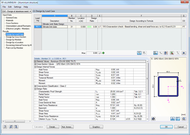
W pierwszym oknie wyników wyświetlane są maksymalne stopnie wykorzystania wraz z odpowiednimi obliczeniami dla każdego obliczanego przypadku obciążenia i kombinacji.
W pozostałych oknach wyświetlane są wszystkie wyniki szczegółowe uporządkowane według określonych tematów. Wzdłuż prętów można wyświetlić wszystkie wyniki pośrednie dla każdego położenia. W ten sposób można łatwo prześledzić, jak w module zostały przeprowadzone poszczególne obliczenia.
Pełne dane modułu stanowią część protokołu wydruku programu RFEM/RSTAB. Użytkownik może dostosować zawartość protokołu i żądany zakres wyników dla poszczególnych warunków projektowych.
- 002459
- Ogólne informacje
- Projektowanie konstrukcji aluminiowych RFEM 6
- Projektowanie konstrukcji aluminiowych RSTAB 9
Rozszerzenie Skręcanie skrępowane (7 stopni swobody) umożliwia przeprowadzanie obliczeń konstrukcji prętowych w programach RFEM i RSTAB, z uwzględnieniem deplanacji przekrojów. Wszystkie siły wewnętrzne (N, Vu, Vv, Mt, pri, Mt, sec, Mu, Mv, Mω) określone w ten sposób mogą zostać uwzględnione w analizie naprężeń zastępczych dla obliczeń konstrukcji aluminiowych. Uwaga: Ta funkcja nie jest jeszcze dostępna dla norm projektowych ADM 2020.
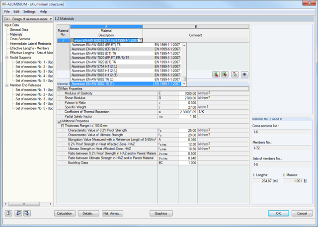
Dane dotyczące materiału, obciążeń i kombinacji obciążeń określone w programie RFEM/RSTAB muszą być zgodne z założeniami obliczeniowymi Eurokodu. Biblioteka materiałów programu RFEM/RSTAB zawiera już odpowiednie materiały. Ponadto RFEM/RSTAB umożliwia automatyczne tworzenie kombinacji obciążeń i wyników zgodnie z Eurokodem. Możliwe jest również ręczne tworzenie kombinacji.
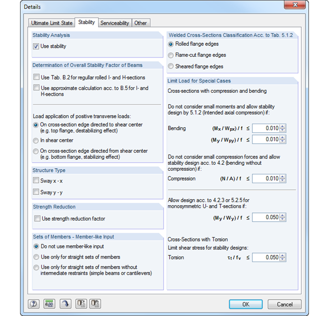
W module dodatkowym RF-/ALUMINIUM należy najpierw wybrać, które pręty i zbiory prętów mają zostać obliczone, a także przypadki obciążeń, kombinacje obciążeń i kombinacje wyników. W dalszych krokach można dostosować wstępnie zdefiniowane ustawienia dla bocznych podpór pośrednich i długości efektywnych.
W przypadku stosowania prętów ciągłych można zdefiniować indywidualne warunki podparcia i mimośrody dla każdego węzła pośredniego poszczególnych prętów. Specjalne narzędzie MES określa obciążenia krytyczne i momenty wymagane do analizy stateczności.
- Obliczenia na rozciąganie, ściskanie, zginanie, ścinanie i kombinację sił wewnętrznych
- Analiza stateczności dla wyboczenia giętnego, wyboczenia skrętnego i zwichrzenia
- Automatyczne określanie krytycznych obciążeń wyboczeniowych i momentu krytycznego dla zwichrzenia za pomocą zintegrowanego programu MES (analiza wartości własnej) na podstawie warunków brzegowych obciążeń i podpór
- Możliwość zastosowania oddzielnych podpór bocznych do belek
- Automatyczna klasyfikacja przekrojów
- Integracja parametrów z załączników krajowych dla następujących krajów:
-
DIN EN 1999-1-1/NA:2010-12 (Niemcy)
-
NBN EN 1999-1-1/ANB:2011-03 (Belgia)
-
DK EN 1999-1-1/NA:2013-05 (Dania)
-
SFS EN 1999-1-1/NA:2016-12 (Finlandia)
-
ELOT EN 1999-1-1/NA:2010-11 (Grecja)
-
IS EN 1999-1-1/NA:2010-03 (Irlandia)
-
UNI EN 1999-1-1/NA:2011-02 (Włochy)
-
LST EN 1999-1-1/NA:2011-09 (Litwa)
-
UNI EN 1999-1-1/NA:2011-02 (Włochy)
-
NEN EN 1999-1-1/NB:2011-12 (Holandia)
-
PN EN 1999-1-1/NA:2011-01 (Polska)
-
SS EN 1999-1-1/NA:2011-04 (Szwecja)
-
STN EN 1999-1-1/NA:2010-01 (Słowacja)
-
BS EN 1999-1-1/NA:2009 (Wielka Brytania)
-
STN EN 1999-1-1/NA:2009-02 (Słowacja)
-
CYS EN 1999-1-1/NA:2009-07 (Cypr)
-
- Obliczenia w stanie granicznym użytkowalności dla charakterystycznej, częstej lub quasi-stałej sytuacji obliczeniowej
- Uwzględnienie spoin poprzecznych
- Różnorodność dostępnych przekrojów; na przykład dwuteowniki, ceowniki, prostokątne profile zamknięte, przekroje kwadratowe, kątowniki o jednakowych i nierównych ramionach, stal płaska, pręty okrągłe
- Przejrzyście ułożone tabele wyników
- Automatyczna optymalizacja przekrojów
- Szczegółowe dokumentowanie wyników z odniesieniem do równań obliczeniowych używanych i opisanych w normie
- Opcje filtrowania i sortowania wyników, w tym listy wyników według prętów, przekrojów i miejsc x lub przypadków obciążeń, kombinacji obciążeń i kombinacji wyników
- Tabela wyników dla smukłości prętów i głównych sił wewnętrznych
- Wykaz części z parametrami masy i masy
- Pełna integracja z programem RFEM/RSTAB
- Jednostki metryczne i anglosaskie

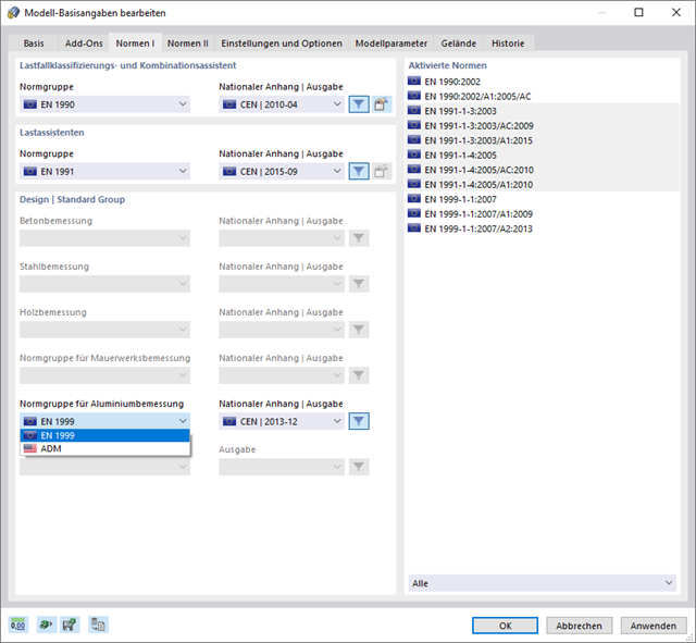
Dzięki oprogramowaniu Dlubal można bezpiecznie i łatwo planować konstrukcje na całym świecie. Wybierz jedną z wielu norm w Danych ogólnych. Można również zdecydować, czy kombinacje mają być tworzone automatycznie.
Dostępne są poniższe normy:
-
EN 1990
-
EN 1990 | Drewno
-
EN 1990 | Mosty drogowe
-
EN 1990 | Suwnice
-
EN 1990 | Geotechnika
-
EN 1990 | Podstawa + drewno
-
EN 15512
-
ASCE 7
-
ASCE 7 | Drewno
-
ACI 318
-
IBC
-
CAN/CSA
-
NBC
-
NBC | Drewno
-
NBR 8681
-
IS 800
-
SIA 260
-
SIA 260 | Drewno
-
BS 5950
-
GB 55001 | GB 55002
-
GB 50009 | GB 50011
-
GB 50068 | GB 50011
-
CTE DB-SE
-
 SANS 10160-1
 -
 NTC
NTC -
NTC | Drewno
-
 AS/NZS 1170.0
 -
 SP 20.13330:2016
 -
 TSC | Stal
W przypadku norm europejskich (EC) dostępne są następujące załączniki krajowe:
-
DIN | 2012-08 (Niemcy)
-
CEN | 2010-04 (Unia Europejska)
-
BDS | 2013-03 (Bułgaria)
-
BS | 2009-06 (Wielka Brytania)
-
ČSN | 2015-05 (Republika Czeska)
-
CYS | 2010-06 (Cypr)
-
DK | 2013-09 (Dania)
-
ELOT | 2009-01 (Grecja)
-
 EVS-EN 1990:2002+NA:2002 (Estonia)
 -
IS | 2010-04 (Irlandia)
-
LST | 2012-01 (Litwa)
-
LU | 2020-03 (Luksemburg)
-
LVS | 2015-01 (Łotwa)
-
MS | 2010-02 (Malezja)
-
NBN | 2015-05 (Belgia)
-
NEN | 2011-12 (Holandia)
-
NF | 2011-12 (Francja)
-
NP | 2009-12 (Portugalia)
-
 NS | 2016-05 (Norwegia)
 -
ÖNORM | 2013-03 (Austria)
-
PN | 2010-09 (Polska)
-
SFS | 2010-09 (Finlandia)
-
SIST | 2010-08 (Słowenia)
-
SR | 2006-10 (Rumunia)
-
SS | 2008-06 (Singapur)
-
SS | 2019-01 (Szwecja)
-
STN | 2010-01 (Słowacja)
-
TKP | 2011-11 (Białoruś)
-
UNE | 2010-07 (Hiszpania)
-
UNI | 2010-10 (Włochy)
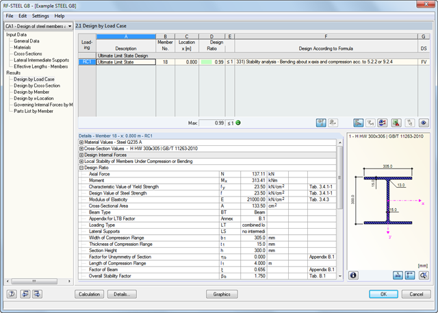
Dane dotyczące materiałów, obciążeń i kombinacji obciążeń muszą zostać wprowadzone w programie RFEM/RSTAB zgodnie z założeniami obliczeniowymi opisanymi w GB 50017. Biblioteka materiałów programu RFEM/RSTAB zawiera już odpowiednie materiały.
W module RF-/STEEL GB wybiera się najpierw pręty i zbiory prętów, które mają zostać obliczone, a także przypadki obciążeń, kombinacje obciążeń i kombinacje wyników.
W kolejnych oknach wprowadzania można dostosować wstępnie zdefiniowane ustawienia bocznych podpór pośrednich i długości efektywnych. Ustawienie to jest następnie wykorzystywane przez program do określenia obciążeń i momentów krytycznych wymaganych do analizy stateczności w takich sytuacjach.

- 002458
- Ogólne informacje
- Projektowanie konstrukcji aluminiowych RFEM 6
- Projektowanie konstrukcji aluminiowych RSTAB 9
Wiesz na pewno, że podczas łączenia elementów rozciąganych za pomocą połączeń śrubowych należy wziąć pod uwagę osłabienie przekroju spowodowane otworami na śruby. Programy do analizy statyczno-wytrzymałościowej również mają na to rozwiązanie. W rozszerzeniu Aluminium Design można wprowadzić lokalną redukcję przekroju pręta. Redukcję przekroju należy wprowadzić jako wartość bezwzględną lub jako procent powierzchni całkowitej.
- 002463
- Ogólne informacje
- Projektowanie konstrukcji aluminiowych RFEM 6
- Projektowanie konstrukcji aluminiowych RSTAB 9
W przypadku obliczeń zgodnie z Eurokodem 9, można znaleźć parametry zintegrowanych załączników krajowych dla następujących krajów:
-
DIN EN 1999-1-1/NA:2021-03 (Niemcy)
-
ÖNORM EN 1999-1-1/NA:2017-11 (Austria)
-
SN EN 1999-1-1/NA:2015-01 (Szwajcaria)
-
BDS EN 1999-1-1/NA:2014-05 (Bułgaria)
-
BS EN 1999-1-1/NA:2014-03 (Wielka Brytania)
-
CEN 1999-1-1/2013-12 (Unia Europejska)
-
CYS EN 1999-1-1/NA:2019-08 (Cypr)
-
CZE EN 1999-1-1/NA:2015-09 (Republika Czeska)
-
DS EN 1999-1-1/NA:2019-09 (Dania)
-
ELOT EN 1999-1-1/NA:2013-12 (Grecja)
-
EVS EN 1999-1-1/NA:2014-01 (Estonia)
-
 HRN EN 1999-1-1/NA:2015-02 (Chorwacja)
 -
I S. EN 1999-1-1/NA:2015-01 (Irlandia)
-
ILNAS EN 1999-1-1/NA:2013-12 (Luksemburg)
-
 IST EN 1999-1-1/NA:2014-03 (Islandia)
 -
LST EN 1999-1-1/NA:2014-03 (Litwa)
-
LVS EN 1999-1-1/NA:2015-01 (Łotwa)
-
 MSZ EN 1999-1-1/NA:2014-04 (Węgry)
 -
NBN EN 1999-1-1/NA:2014-01 (Belgia)
-
NEN EN 1999-1-1/NA:2014-01 (Holandia)
-
NF EN 1999-1-1/NA:2016-07 (Francja)
-
NP EN 1999-1-1/NA:2014-11 (Portugalia)
-
NS EN 1999-1-1/NA:2014-04 (Norwegia)
-
PN EN 1999-1-1/NA:2014-05 (Polska)
-
SFS EN 1999-1-1/NA:2018-01 (Finlandia)
-
SIST EN 1999-1-1/NA:2014-05 (Słowenia)
-
SR EN 1999-1-1/NA:2015-01 (Rumunia)
-
SS EN 1999-1-1/NA:2013-12 (Szwecja)
-
STN EN 1999-1-1/NA:2014-05 (Słowacja)
-
TKP EN 1999-1-1/NA:2010-01 (Białoruś)
-
UNE EN 1999-1-1/NA:2014-01 (Hiszpania)
-
UNI EN 1999-1-1/NA:2014-02 (Włochy)

- 002465
- Wyniki
- Projektowanie konstrukcji aluminiowych RFEM 6
- Projektowanie konstrukcji aluminiowych RSTAB 9
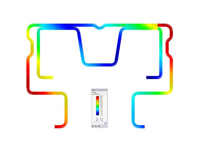
Czy projekt zakończył się sukcesem? Bardzo dobrze, teraz zaczyna się część zrelaksowana. Ponieważ program przedstawia przeprowadzone weryfikacje w formie tabelarycznej. Można wyświetlić szczegółowe informacje o wszystkich wynikach. Dzięki przejrzyście przedstawionym wzorom weryfikacyjnym można bez problemu zrozumieć wyniki. W oprogramowaniu Dlubal nie występuje efekt czarnej skrzynki.
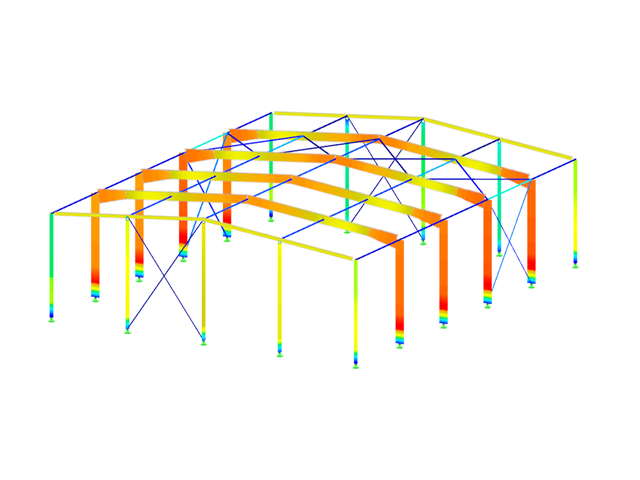
Kontrole są przeprowadzane we wszystkich istotnych punktach prętów i wyświetlane graficznie jako profil wyników. Bardziej szczegółowe grafiki można znaleźć w wynikach wyszukiwania. Obejmuje to na przykład profil naprężenia w przekroju lub kształt drgań własnych.
Wszystkie dane wejściowe i wyniki są częścią protokołu wydruku programu RFEM/RSTAB. Dla poszczególnych obliczeń można wybrać zawartość raportu i żądaną głębokość danych wyjściowych.
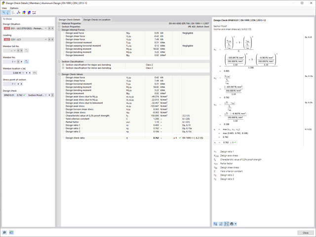
Pierwsza tabela przedstawia maksymalne stopnie wykorzystania wraz z odpowiednim wykorzystaniem dla każdego obliczanego przypadku, grupy i kombinacji obciążeń.
Kolejne tabele pokazują wszystkie szczegółowe wyniki posegregowane według określonych kryteriów w rozwijanych elementach menu. Wszystkie wyniki pośrednie wzdłuż prętów można wyświetlić w dowolnym miejscu. W ten sposób można łatwo prześledzić, jak w module zostały przeprowadzone poszczególne obliczenia.
Pełne dane modułu stanowią część protokołu wydruku programu RFEM/RSTAB. Użytkownik może dostosować zawartość protokołu i żądany zakres wyników dla poszczególnych warunków projektowych.
- Obliczenia na rozciąganie, ściskanie, zginanie, ścinanie i kombinację sił wewnętrznych
- Analiza stateczności dla wyboczenia giętnego i zwichrzenia
- Automatyczne określanie krytycznych obciążeń wyboczeniowych i współczynników stateczności dla zwichrzenia zgodnie z Załącznikiem B
- Możliwość zastosowania oddzielnych podpór bocznych do belek
- Automatyczna analiza stateczności lokalnej i sprawdzenie kryteriów projektowania plastycznego przekroju
- Analiza deformacji (użytkowalność)
- Optymalizacja przekroju
- Szeroki wybór przekrojów, takich jak dwuteowniki walcowane, ceowniki, przekroje zamknięte prostokątne, kątowniki, teowniki. Przekroje spawane: Dwuteowe (symetryczne i asymetryczne względem mocnej osi), ceowniki (symetryczne względem mocnej osi), prostokątne przekroje zamknięte (symetryczne i asymetryczne względem mocnej osi), kątowniki, rury okrągłe i pręty okrągłe
- Przejrzyście ułożone tabele wyników
- Szczegółowa dokumentacja wyników wraz z odniesieniami do równań obliczeniowych z zastosowanej normy
- Różne opcje filtrowania i sortowania wyników, w tym wyświetlanie wyników według prętów, przekrojów, położenia x lub przypadków obciążenia, kombinacji obciążeń i kombinacji wyników
- Tabela wyników dla smukłości pręta i głównych sił wewnętrznych
- Wykaz części z parametrami masy i masy
- Pełna integracja z programem RFEM/RSTAB
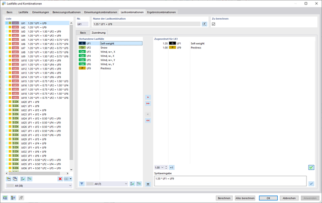
W oknie dialogowym "Przypadki obciążeń i kombinacje" istnieje możliwość automatycznego generowania kombinacji obciążeń i wyników po wybraniu odpowiednich reguł kombinacji. W przejrzyście zorganizowanym oknie można na przykład kopiować lub dodawać przypadki obciążeń.
Dodatkowo w tabelach można zarządzać przypadkami i kombinacjami obciążeń.

- 002140
- Ogólne informacje
- Projektowanie konstrukcji aluminiowych RFEM 6
- Projektowanie konstrukcji aluminiowych RSTAB 9
- Szeroki wybór dostępnych przekrojów, takich jak dwuteowniki walcowane; ceowniki; teowniki; kątowniki; profile zamknięte prostokątne i okrągłe; pręty okrągłe; przekroje symetryczne i niesymetryczne, parametryczne przekroje dwuteowe, teowe, kątowniki; przekroje złożone (przydatność do obliczeń zależy od wybranej normy)
- Wymiarowanie ogólnych przekrojów RSECTION (w zależności od formatów obliczeniowych dostępnych w odpowiedniej normie); na przykład obliczanie naprężeń zastępczych
- Wymiarowanie prętów o zbieżnym przekroju (metoda zależna od normy)
- Możliwe jest dostosowanie istotnych współczynników obliczeniowych i parametrów normowych
- Elastyczność dzięki szczegółowym opcjom ustawień dla podstawy i zakresu obliczeń
- Szybkie i przejrzyste wyświetlanie wyników dla globalnej oceny ich rozkładu na konstrukcji po zakończeniu obliczeń
- Szczegółowe wyniki obliczeń i niezbędne wzory (jasna i łatwa do zweryfikowania ścieżka wyników)
- Przejrzyste zestawienie wyników w formie numerycznej w stosownych oknach oraz możliwość ich graficznego przedstawienia na konstrukcji
- Integracja wyników z protokołem wydruku programu RFEM/RSTAB