Home Downloads & Info References Customer Projects Revitalization and Extension of Supporting Structure of Stage Roof in State Playhouse Dresden, Germany
Revitalization and Extension of Supporting Structure of Stage Roof in State Playhouse Dresden, Germany
Customer Project
The theater built from 1911 to 1913 has a varied history. The building was destroyed by the allied air attacks in February 1945, reconstructed in the post‑war years, and damaged by floods in August 2002. Within an 18‑week break, the Dresden theater has been extensively renovated and modernized.
Investor |
Saxonian Real Estate and Construction Management Dresden, Germany www.sib.sachsen.de |
Project Planning | Architekturbüro Wagner Dresden, Germany |
Structural Design |
KREBS+KIEFER Ingenieure GmbH, Germany www.kuk.de |
- Length: ~ 108 ft
- Width: ~ 52.6 ft
- Height: ~ 30 ft
- Weight: ~ 16 t
- Number of Nodes: 2,516
- Members: 4,077
- Materials: 4
- Cross-Sections: 91
Model
Due to the short time limit, there were up to 230 workers on site, working in three shifts. The reconstruction included, among others, the renovation of the stage equipment and strengthening the roof structure of the stage tower. KREBS+KIEFER engineers scrutinized the stability of the stage roof using RSTAB. The stability analysis detected deficiencies in load‑bearing capacity, which required reinforcement measures.
Roof Structure of Stage Tower
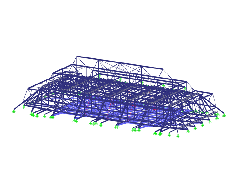
The total height of the stage tower is about 38 m, measured from the stage floor to the top of the roof. The primary structure of the roof consists of five steel trusses arranged parallel to each other. The trusses have a height of 4.10 m and a span of about 32.2 m, and are placed on reinforced concrete columns. The top chord nodes of the outer truss girder are partially braced on the existing walls by inclined members. Together with the members perpendicular to the trusses, an additional load transfer occurs in the transverse direction, which can be taken into account by 3D modelling in RSTAB.
Recalculation
In the bottom chord plane of the truss girder, there is a new fly loft including twelve point hoists with a self-weight of 4.0 kN, among other things. Rope lines are used for moving loads of up to 1.1 kip, such as stage sets, decorations, lighting equipment, etc. Furthermore, the old machines were replaced by new, heavier ones, and various imposed loads were increased.
For the design of structural components and connections, the acting internal forces in the current state were determined in the analytical model. In another model, all new structural components were added and the newly entered permanent and variable loads were applied. Using super combinations, it was possible to superimpose the internal forces and perform the ultimate limit state design.
The structural recalculation for the final state after installing the new stage equipment resulted in overloading various structural members. This required the implementation of various reinforcement measures. For example, the load of the most loaded outer truss girders was reduced by implementing diagonal bracing to the adjacent trusses in the transversal direction. Also, numerous site joints and node areas had to be reinforced by arranging supplementary metal plates and replacing rivets by fitted bolts with a higher load-bearing capacity.
On 29. October 2016, the successful renovation project with the total cost of € 11 million was celebrated by performing Shakespeare's Othello.
Source:
[1] Stroetmann, R., Fuchs, A., Oertel, R.: Schauspielhaus Dresden - Revitalisierung und Ausbau der Tragkonstruktion des Bühnendaches. In: Stahlbau 11-2017, pages: 972-985, published by Ernst & Sohn
Project Location
Theaterstraße 2Contact us
Do you have questions or need advice?
Contact our free e-mail, chat, or forum support or find various suggested solutions and useful tips on our FAQ page.
Recommended Events
Eurocode 3 | Steel structures according to DIN EN 1993-1-1
Online Training 05/06/2021 8:30 AM - 12:30 PM CEST
Eurocode 5 | Timber structures according to DIN EN 1995-1-1
Online Training 05/20/2021 8:30 AM - 12:30 PM CEST
Designing Cold-Formed Steel Sections According to Eurocode 3
Webinar 04/30/2020 3:00 PM - 3:45 PM CEST
Videos
Models to Download
Knowledge Base Articles

New
In RF-/FOUNDATION Pro, the user can freely select the proportion of the relieving soil pressure by means of the factor kred.Screenshots
RF-/DYNAM Pro - Natural Vibrations Add-on Module for RFEM/RSTAB | Determination of natural frequencies and mode shapes
RF-/PLATE-BUCKLING Add-on Module for RFEM/RSTAB | Plate Buckling Analysis for Plates with or Without Stiffeners According to 1993-1-5
RFEM/RSTAB Add-on Module RF-IMP/RSIMP | Generation of Geometric Replacement Imperfections and Pre-deformed Replacement Structures
Extension of the RF-/STEEL Warping Erosion module | Lateral -torsional buckling analyzes of members according to the second -order theory with 7 degrees of freedom
RFEM/RSTAB add-on module RF-/TOWER effective lengths | Determination of effective lengths of lattice towers
RFEM add-on module RF-CONCRETE NL | Nonlinear reinforced concrete calculation for the serviceability limit state
RFEM/RSTAB add-on module RF-/JOINTS Steel-Column Base | Hinged and restrained column bases according to EC 3
RF-/DYNAM Pro-Natural Vibrations Add-on Module for RFEM/RSTAB | Determination of Natural Frequencies and Mode Shapes
RFEM/RSTAB add-on module RF-/STEEL BS | Design of steel members according to BS 5950 or BS EN 1993-1-1
Product Features Articles

SHAPE-THIN determines the effective cross-sections according to EN 1993-1-3 and EN 1993-1-5 for cold-formed sections. You can optionally check the geometric conditions for the applicability of the standard specified in EN 1993‑1‑3, Section 5.2.
The effects of local plate buckling are considered according to the method of reduced widths and the possible buckling of stiffeners (instability) is considered for stiffened sections according to EN 1993-1-3, Section 5.5.
As an option, you can perform an iterative calculation to optimize the effective cross-section.
You can display the effective cross-sections graphically.
Read more about designing cold-formed sections with SHAPE-THIN and RF-/STEEL Cold-Formed Sections in this technical article: Design of a Thin-Walled, Cold-Formed C-Section According to EN 1993-1-3.
Frequently Asked Questions (FAQ)
- I am trying to manually check the deformations from the CRANEWAY add-on module. However, I obtain great deviations. How to explain the differences?
- What should be considered when using a failure of columns under tension in the RF‑/DYNAM Pro – Equivalent Loads add-on module?
- Why is there no stability analysis displayed in the results despite the activation of the stability analysis in RF‑/STEEL EC3?
- How can I model and design a crane runway girder with Dlubal Software?
- Is it possible to set user-defined values when viewing solid stress results?
- Why do I get large differences for the design of a longitudinally stiffened buckling panel in comparison with the German and Austrian National Annex?
- How are the signs for the release results of a line release and line hinges interpreted?
- How can I create a curved or arched section?
- How are hot-dip galvanized components considered for fire resistance in the RF‑/STEEL EC3 add-on module?
Customer Projects
Programs Used for Structural Analysis