


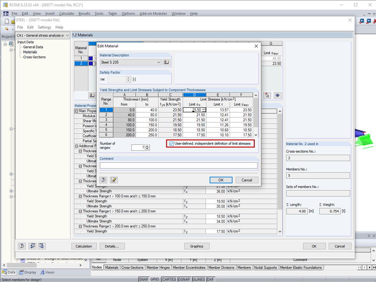
To do this, click the [Edit Material] button. In the "Edit material" window, you can then define the limit stresses using the yield strength or by selecting "Manual definition of limit stresses independent of yield strength" (Image 01).

Sign up for the Dlubal Extranet to get most of the software and have exclusive access to your personal data.
Sign up for the Dlubal Extranet to get most of the software and have exclusive access to your personal data.
Sign up for the Dlubal Extranet to get most of the software and have exclusive access to your personal data.
To do this, click the [Edit Material] button. In the "Edit material" window, you can then define the limit stresses using the yield strength or by selecting "Manual definition of limit stresses independent of yield strength" (Image 01).
Ms. von Bloh provides technical support for our customers and is responsible for the development of the SHAPE‑THIN program as well as steel and aluminum structures.