Due to this structural design, a lateral and torsional restraint cannot be assumed here when determining the ideal elastic critical moment during the stability analysis. This reduces the structural resistance and, therefore, has to be considered. On the other hand, the ultimate load-increasing-capacity effect of the rotational restraint from the trapezoidal sheeting is taken into account.
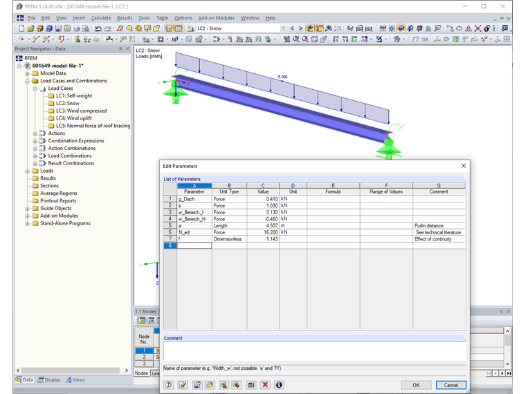
The model of this technical article is based on Example 1.3 Roof Purlin in the technical literature [1]. The roof purlins are single-span beams between the roof trusses and have a length of 9.0 m and an inclination of 3.18°.
Loading and Internal Forces
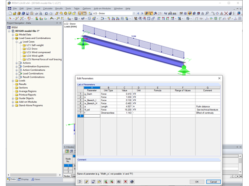
The continuous trapezoidal sheeting lies on five roof purlins with an application width of approximately 4.50 m. According to the relevant tables in the technical literature for continuous beams, the factor for the support load B is 1.143. Take the characteristic values of the surface loads for self-weight, snow, and wind from [1]. The input or the calculation of the resulting member loads is performed using the parametrization available in RFEM and RSTAB.
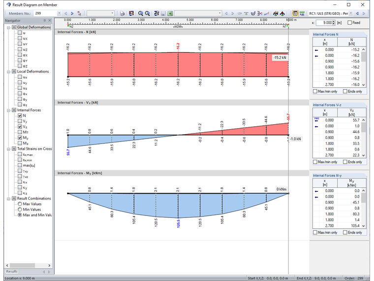
The automatic combinatorics in RFEM/RSTAB are only performed for the ultimate limit state according to Equation 6.10 of EN 1990. The following design internal forces result from the generated load combinations.
Calculating the Ideal Elastic Critical Moment and Stability Analysis
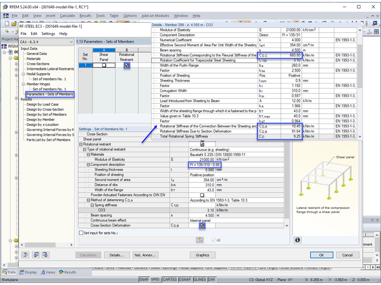
To determine Mcr according to the eigenvalue method, we create an internal member model with four degrees of freedom in the RF-/STEEL EC3 add-on module. Since no lateral and torsional restraint can be assumed due to the formation without stiffeners outside the bracing panels, we have to calculate the rotational restraint resulting from the cross-section deformation of the purlin. This is done according to [5] as follows.
where
A much more complex method can be found in [6].
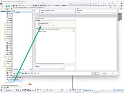
Furthermore, we consider the ultimate load-increasing capacity of the trapezoidal sheeting (135/310-0.88 in the positive position). The effective rotational restraint CD is automatically calculated in RF-/STEEL EC3 according to [3], Equation E.11 if you enter the corresponding data in input tables 1.12 and 1.13.
where
These values can be used to perform the stability analysis according to the analytical methods described in [2], Section 6.3. Due to the low roof inclination, the component in the direction of the minor axis can be neglected. Thus, it would be possible to perform the design according to Section 6.3.3 "Uniform members in bending and axial compression" or Section 6.3.4 "General method for lateral and lateral torsional buckling of structural components".
Due to the simpler input of the support conditions in this case, we select the method according to Section 6.3.4. If the moment around the minor axis can no longer be neglected, we would have to select the method according to Section 6.3.3.
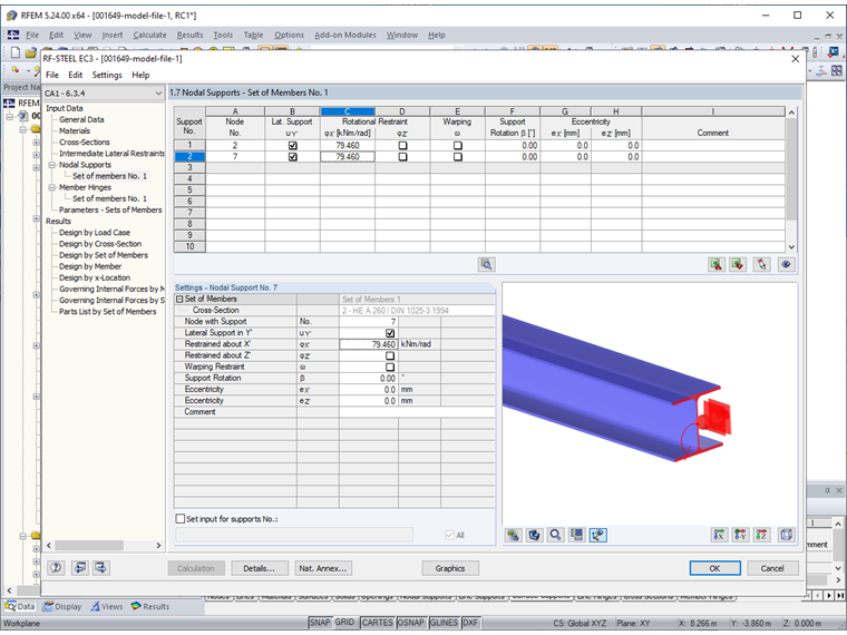
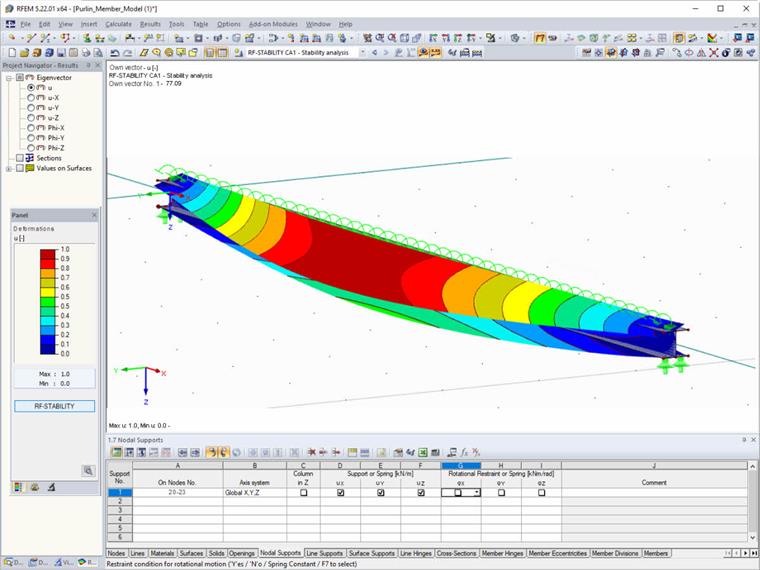
The following figure shows the required entries of the nodal supports for the eigenvalue method (internal member model with four degrees of freedom).
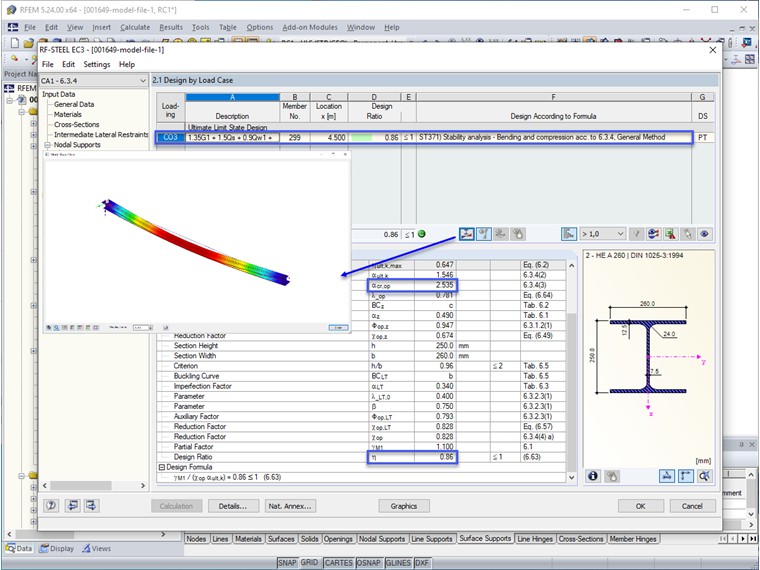
The ultimate limit state of the roof purlin can be verified by the General Method. The critical load factor for CO 3 and the defined system is calculated as 2.535. You can also display the corresponding mode shape graphically.
The ideal elastic critical moment is thus calculated as follows:
Calculating the Ideal Elastic Critical Moment on the Surface Model
A surface model is used to validate the ideal elastic critical moment Mcr. You can create this kind of model in RFEM with just a few mouse clicks, using the "Generate Surfaces from Member" function. With the RF-STABILITY add-on module, a critical load factor of 2.55 is calculated for the governing load combination 3 and thus results in:


.png?mw=600&hash=49b6a289915d28aa461360f7308b092631b1446e)


