


User Story
In the first example, we proceed with a preliminary design, focusing particularly on calculating the total force. It is selected as a 2D square plane. It belongs to Group 1 of WTG-Merkblatt-M3:
- G1: Qualitative values with low accuracy requirements for use in the basic investigation or preliminary design. The effort and the requirements for the level of detail are reduced, as often not all boundary conditions are fully clarified.
- R1: Solitary (without surrounding buildings), analysis of individual important wind directions.
- Z1: Statistical mean values, provided these concern stationary flow processes where fluctuations (e.g., due to approaching flow turbulence) can be sufficiently captured by other measures.
- S1: Static effects. It is sufficient to represent the structural model with the necessary mechanical detail, but without mass and damping properties.
The dimensions of the example are shown in Figure 1, and the input assumption is illustrated in Table 1:
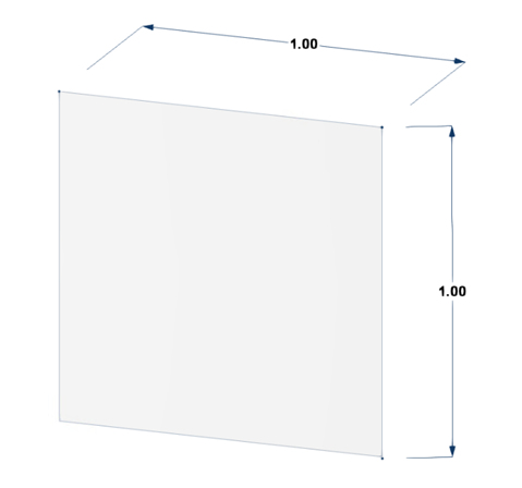
Table 1: Input Data of 2D Square Plane Verification Example
| Model | 2D square plane |
|---|---|
| Dimension | a = 1 m |
| Basic wind speed | V = 30 m/s |
| Air density | ρ = 1.225 kg/m³ |
| Solver | Pressure-Based |
| Turbulence model | Steady k-ω SST |
| Terrain Category | 2 |
| Type of wind velocity profile in RFEM | Peak |
| Numerical algorithm | SIMPLE algorithm |
| Discretization | Second-Order |
| Residual pressure | 10⁻⁴ |
| Kinematic viscosity | ν = 1.5 × 10⁻⁵ |
In this example, we will compare the wind force values between EN 1991-1-4 and RWIND. The wind force formula in Eurocode Section 5.3 is defined:
|
cscd |
Structural factor |
|
cf |
Force coefficient for the structure or structural element |
|
qp(ze ) |
Peak velocity pressure at reference height ze |
|
Aref |
Reference area of the structure or structural element |
Force coefficients (d=b=1 → Cf,0=2.10) of rectangular sections with sharp corners and without free end flow can be obtained in Figure 7.23 in EN 1991-1-4, and the reduction factor (ψr) for a square cross-section with rounded corners (r/b=0 → ψ r=1) can be obtained from Figure 7.24 in EN 1991-1-4. Indicative values of the end-effect factor ψλ=0.63 as a function of the solidity ratio φ=1 versus slenderness λ=2 can be obtained in Figure 7.36 in EN 1991-1-4.
The force coefficient cf of the structural elements of the rectangular section with the wind blowing normally on a flat surface should be determined by Expression (7.9) in EN 1991-1-4:
|
cf,0 |
The force coefficient of rectangular sections with sharp corners and without free-end flow |
|
ψr |
The reduction factor for square sections with rounded corners |
|
ψλ |
The end-effect factor for elements with free-end flow |
- Mean wind velocity
The mean wind velocity vm (ze) at reference height z_e depends on the terrain roughness, terrain orography, and basic wind velocity vb. It is determined using EN1991-1-4 equation (4.3):
- Wind turbulence
The turbulence intensity Iv (ze) at reference height ze is defined as the standard deviation of the turbulence divided by the mean wind velocity. It is calculated in accordance with EN1991-1-4 Equation 4.7. For the examined case ze smaller than zmin:
- Basic velocity pressure
The basic velocity pressure q_b is the pressure corresponding to the wind momentum determined at the basic wind velocity vb. The basic velocity pressure is calculated according to the fundamental relation specified in EN1991 -14 §4.5(1):
where ρ is the density of the air in accordance with EN1991-1-4 §4.5(1). In this calculation, the following value is considered ρ=1.225 kg/m3.
- Peak velocity pressure
The peak velocity pressure qp (ze) at reference height ze includes mean and short-term velocity fluctuations. It is determined according to EN1991-1-4 Equation 4.8:
Then the wind force can be calculated:
Image 2 shows a mesh sensitivity study in RWIND for the 2D plate. As mesh density increases from 10% to 40%, the force coefficient Cf decreases and stabilizes at 1.23 from 30% onward, indicating mesh-independent results and ensuring simulation accuracy without unnecessary refinement.

Also, the computational mesh study needs to be performed according to the following link:
The WTG-Merkblatt M3 provides two key methods for validating simulation results. The Hit Rate Method evaluates how many of the simulated values Pi correctly match the reference values Oi within a defined tolerance, using a binary classification approach (hit or miss). This approach assesses the reliability of the simulation by calculating a hit rate q, similar to confidence functions used in reliability theory. In contrast, the Normalized Mean Squared Error (e2) method offers a more detailed accuracy assessment by quantifying the average squared deviation between simulated and reference values, normalized to account for scale differences. Together, these methods provide both qualitative and quantitative measures for simulation validation.
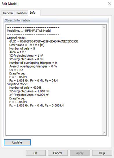
Results in RWIND and Comparison to Eurocode
In RWIND the results of the total forces (in Figures 3 and 4) are available in the Info tab of the Edit model. The difference between RWIND and the Eurocode is about Wrel = 2.45% (less than the mentioned criteria in WTG); then the hit rate can be obtained as q=100%, which shows good agreement. The low normalized mean square error e2=0.0005 confirms strong agreement between simulation and measurements, meeting the validation standards effectively.

Here is the 3D model of the 2D plate:
