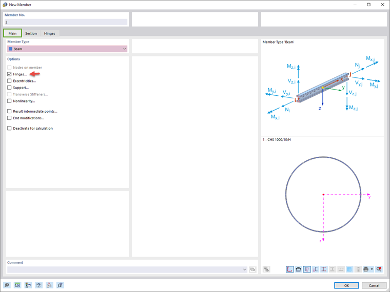
The procedure described in Chapter Beam-Column also applies to creating the bracing. Open the "New Member" dialog box and create a member with the "Beam" type.
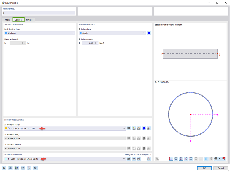
Define the cross-section and the material of the bracing member in the same way as for the beam-column. The cross-section of the bracing element is a thin-walled pipe section with a diameter of 600 mm and a thickness of 10 mm. The material is again steel S355.
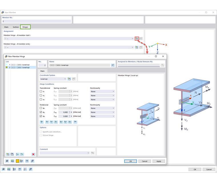
If you activated the "Hinges" option as shown in Image New Member when creating the member, you can define the hinge properties of the bracing member in the "Hinges" tab. For this member, a hinge should be defined around the local axes y and z at the base (see Image New Member Hinge).
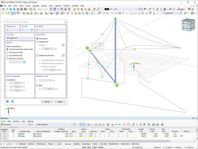
Finally, position the member in the work window: Place the start point in the base of the column and the end point in the outer intersection of the DXF background lines (see Image Defining Bracing Member).