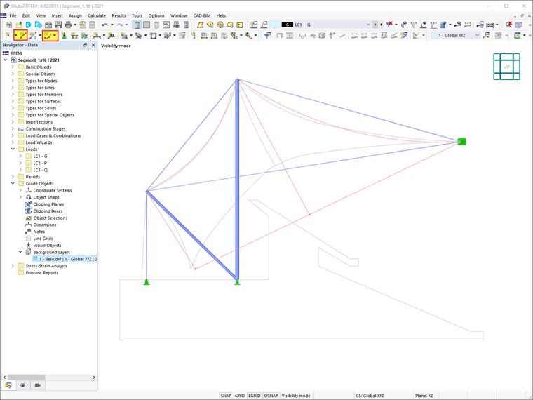
Since the membrane is to be suspended, the next step is to graphically define the membrane boundaries, taking into account the stored DXF data. Activate the background layer (see Chapter Importing DXF File as Background Layer) in order to draw the boundary lines of the membrane. These can be defined as lines
![]() and polylines (arcs)
and polylines (arcs)
![]() , as shown in Image Boundary Lines of Membrane.
, as shown in Image Boundary Lines of Membrane.
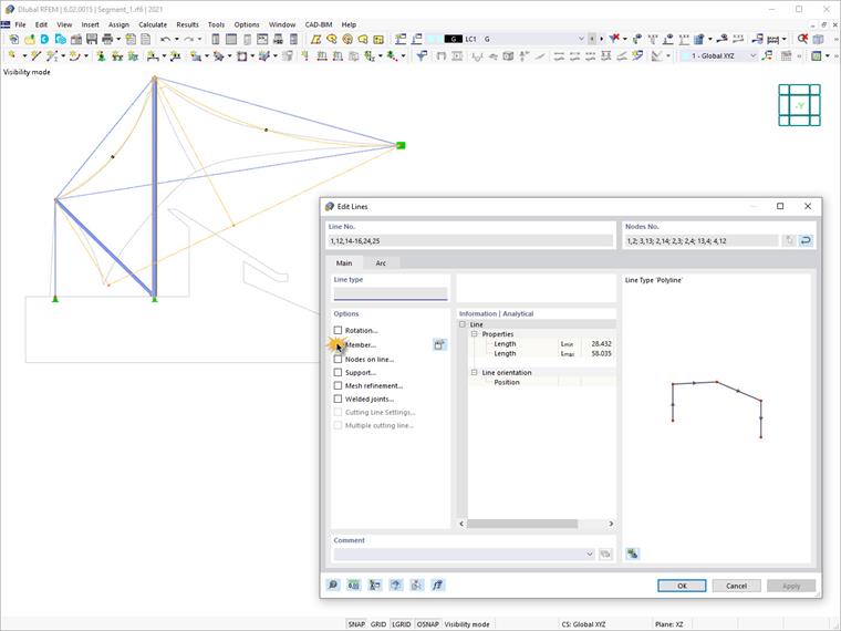
After defining the membrane boundaries, you can assign members to these lines via Select → right-click → Edit. To do this, activate the Members check box for the selected line(s) in the "Edit Lines" dialog box.
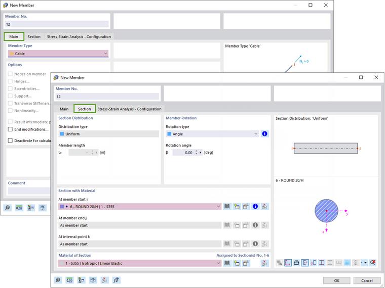
The New Member dialog box appears. Proceed in the same way as when setting the column or the bracing. The member cross-section should be defined as "Round 20/H", as shown in Image Cross-Section of New Member. By confirming the dialog box, you assign the member to the line.