


INTRODUCTION
This article provides guidance on designing moment-resisting joints in accordance with Eurocode 3, specifically targeting bolted end plate connections between beams and columns in multi-story frames. It references relevant sections, figures, and tables from EN 1993-1-8 and other applicable standards as needed.
ANALYTICAL APPROACH
The analytical procedure is taken from [1].
Joint Configuration
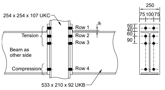
| Column | 254x254x107 UKC | S275 |
| Beam | 533x210x92 UKB | S275 |
| End plate | 670x250x25 mm | S275 |
| Bolt | M24 class 8.8 | |
| Welds | Fillet welds: flange sf = 12 mm, web sw = 8 mm |
Equivalent T-Stub Resistance
The resistance of the equivalent T-stubs is evaluated separately for the end plate and the column flange. The resistances are calculated for three possible modes of failure, and the resistance is taken as the minimum of the values for these three modes.
The design resistance of the T-stub flange for each of the modes is given below.

The modes of failure are shown below:
| where | ||
| ℓeff,1 | is the effective length of the equivalent T-stub for Mode 1, taken as the lesser of ℓeff,cp and ℓeff,nc | |
| ℓeff,2 | is the effective length of the equivalent T-stub for Mode 2, taken as ℓeff,nc | |
| tf | in the thickness of T-stub flange (= tp or tfc) | |
| fy | is the yield strength of the T-stub flange (i.e. of the column or end plate) | |
| ∑Ft,Rd | is the total tension resistance for the bolts in the T-stub (= 2Ft,Rd for a single row) | |
| ew | = dw/4 | |
| dw | is the diameter of the washer or the width across the points of the bolt head | |
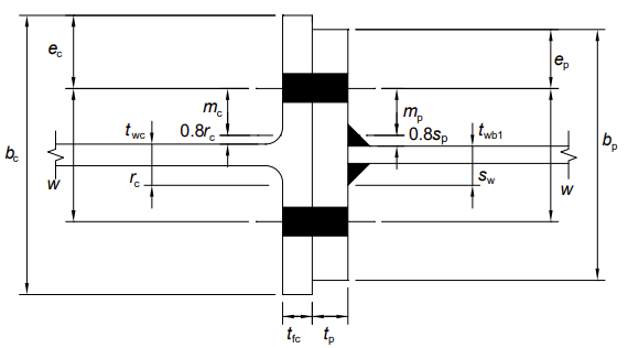
| m | is the distance as defined in the figure above | |
| n | is the minimum of ec (the edge distance of the column flange), ep (the edge distance of the end plate), 1.25 m (for the end plate or the column flange, as appropriate) |
Resistance definition:
Tension Zone T-Stubs
BOLT ROW 1
Column flange in bending (no backing plate)
Consider bolt row 1 acting alone. The key dimensions are shown below.
End plate in bending
Summary of resistance computation:
| Parameter | Unit | Column flange in bending (no backing plate) | Column web in transverse tension | End plate in bending | Beam web in tension | |
| m | [mm] | 33.4 | - | = mx = 30.4 | - | |
| e | [mm] | = emin = 75 | - | e = 75, ex = 50 | - | |
| ℓeff,1 | [mm] | 210 | - | 125 | - | |
| ℓeff,2 | [mm] | 233 | - | 125 | - | |
| MODE 1 | ||||||
| n | [mm] | 41.8 | - | 38.0 | - | |
| tf | [mm] | 20.5 | - | 25 | - | |
| fy | [N/mm2] | 265 | - | 265 | - | |
| Mpl,1,Rd | [Nmm] | 5850x103 | - | 5180x103 | - | |
| dw | [mm] | 39.55 | - | - | - | |
| ew | [mm] | 9.9 | - | 9.9 | - | |
| FT,1,Rd | [kN] | 898 | - | 901 | - | |
| MODE 2 | ||||||
| Mpl,2,Rd | [Nmm] | 6490x103 | - | 5180x103 | - | |
| Ft,Rd | [N] | 203x103 | - | 203x103 | - | |
| Bolt in a row | [pcs] | 2 | - | 2 | - | |
| ∑Ft,Rd | [N] | 406x103 | - | 406x103 | - | |
| FT,2,Rd | [kN] | 398 | - | 377 | - | |
| MODE 3 | ||||||
| FT,3,Rd | [kN] | 406 | - | 406 | - | |
| ω | [-] | - | 1.0 | - | ||
| beff,t,wc | [mm] | - | = ℓeff,2 = 233 | - | ||
| fy,wc | [N/mm2] | - | = fy,c = 265 | - | ||
| RESISTANCE | Ft,fc,Rd | Ft,wc,Rd | Ft,ep,Rd | |||
| [kN] | 398 | 790 | 377 | |||
| NOTE | is not applicable |
The resistance of bolt row 1 is the smallest value of the resistances mentioned above.
Therefore, Ft,1,Rd = min {Ft,fc,Rd = 398; Ft,wc,Rd = 790; Ft,ep,Rd = 377} = 377 kN.
BOLT ROW 2
Firstly, consider row 2 alone.
End plate in bending
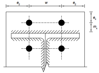
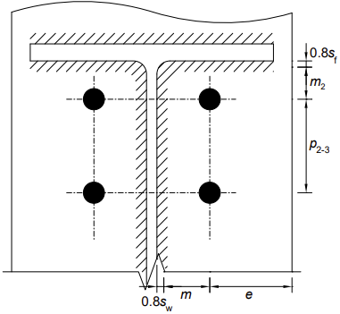
Bolt row 2 is the first bolt row below the beam flange, considered as the 'first bolt row below the tension flange of the beam'. The key dimensions for the T-stub are shown for the column flange T-stub in row 1 and as shown below (in elevation) for row 2.
Summary of resistance computation:
| Parameter | Unit | Column flange in bending | Column web in transverse tension | End plate in bending | Beam web in tension | |
| m | [mm] | - | - | = mp = 38.6 | - | |
| m2 | [mm] | - | - | 34.8 | - | |
| e | [mm] | - | - | = ep = 75 | - | |
| ℓeff,1 | [mm] | - | - | 243 | - | |
| ℓeff,2 | [mm] | - | - | 290 | - | |
| MODE 1 | ||||||
| n | [mm] | - | - | 48.3 | - | |
| tf | [mm] | - | - | 25 | - | |
| fy | [N/mm2] | - | - | 265 | - | |
| Mpl,1,Rd | [Nmm] | - | - | 10.1x10³ | - | |
| ew | [mm] | - | - | 9.9 | - | |
| FT,1,Rd | [kN] | - | - | 1291 | - | |
| MODE 2 | ||||||
| Mpl,2,Rd | [Nmm] | - | - | 12.0x10⁶ | - | |
| Ft,Rd | [N] | - | - | 203x103 | - | |
| Bolt in a row | [pcs] | - | - | 2 | - | |
| ∑Ft,Rd | [N] | - | - | 406x103 | - | |
| FT,2,Rd | [kN] | - | - | 502 | - | |
| MODE 3 | ||||||
| FT,3,Rd | [kN] | - | - | 406 | - | |
| ω | [-] | - | - | - | 1.0 | |
| beff,t,wc | [mm] | - | - | - | 243 | |
| twb | [mm] | - | - | - | 10.1 | |
| fy,wc | [N/mm2] | - | - | - | 675 | |
| RESISTANCE | Ft,fc,Rd | Ft,wc,Rd | Ft,ep,Rd | Ft,wb,Rd | ||
| [kN] | 398 | 790 | 406 | 675 | ||
| NOTE | as calculated for bolt row 1, Mode 2 | as calculated for bolt row 1 |
The resistances for row 2 above all consider the row acting alone. However, on the column side, the resistance may be limited by the resistance of the group of rows 1 and 2. The group resistance is now considered.
ROWS 1 AND 2 COMBINED
Column flange in bending
Summary of resistance computation:
| Parameter | Unit | Column flange in bending | Column web in transverse tension | End plate in bending | |
| m | [mm] | 33.4 | - | - | |
| ℓeff,1 | [mm] | 332 | - | - | |
| ℓeff,2 | [mm] | 332 | - | - | |
| MODE 1 | |||||
| n | [mm] | 41.8 | - | - | |
| tf | [mm] | 20.5 | - | - | |
| fy | [N/mm2] | 265 | - | - | |
| Mpl,1,Rd | [Nmm] | 9.24x10³ | - | - | |
| ew | [mm] | 9.9 | - | - | |
| FT,1,Rd | [kN] | 1420 | - | - | |
| MODE 2 | |||||
| Mpl,2,Rd | [Nmm] | 9.24x10⁶ | - | - | |
| Ft,Rd | [N] | 203 | - | - | |
| Bolts | [pcs] | 4 | - | - | |
| ∑Ft,Rd | [N] | 812 | - | - | |
| FT,2,Rd | [kN] | 697 | - | - | |
| MODE 3 | |||||
| FT,3,Rd | [kN] | 812 | - | - | |
| ω | [-] | - | 1.0 | - | |
| beff,t,wc | [mm] | - | 332 | - | |
| twb | [mm] | - | 12.8 | - | |
| fy,wc | [N/mm2] | - | 265 | - | |
| RESISTANCE | Ft,fc,Rd | Ft,wc,Rd | Ft,ep,Rd | ||
| [kN] | 697 | 1126 | - | ||
| NOTE | There is no group mode for the end plate |
Resistance of bolt rows 1 and 2 is the smallest value of resistances Column flange in bending and Column web in tension, that is Ft,1-2,Rd = min {Ft,fc,Rd = 697; Ft,wc,Rd = 1126} = 697 kN.
The resistance of bolt row 2 on the Column side is therefore limited to Ft2,c,Rd = Ft,1-2,Rd - Ft1,Rd = 697 - 377 = 320 kN.
Resistance of bolt row 2 is the smallest value of resistances: Column flange in bending Ft,fc,Rd = 398 kN, Column web in tension Ft,wc,Rd = 790 kN, Beam web in tension Ft,wb,Rd = 675 kN, End plate in bending Ft,ep,Rd = 406 kN and Column side, as a part of the group, Ft2,c,Rd = 320 kN. Therefore, the resistance of the bolt row 2 Ft,2,Rd = 320 kN.
BOLT ROW 3
Firstly, consider row 3 alone.
Summary of resistance computation:
| Parameter | Unit | Column flange in bending | Column web in transverse tension | End plate in bending | Beam web in tension | |
| e | [mm] | - | - | = ep = 75 | - | |
| m | [mm] | - | - | 38.6 | - | |
| ℓeff,1 | [mm] | - | - | 248 | - | |
| ℓeff,2 | [mm] | - | - | 248 | - | |
| MODE 1 | ||||||
| n | [mm] | - | - | 48.3 | - | |
| tf | [mm] | - | - | 25 | - | |
| fy | [N/mm2] | - | - | 265 | - | |
| Mpl,1,Rd | [Nmm] | - | - | 10.1x10⁶ | - | |
| ew | [mm] | - | - | 9.9 | - | |
| FT,1,Rd | [kN] | - | - | 1291 | - | |
| MODE 2 | ||||||
| Mpl,2,Rd | [Nmm] | - | - | 10.3x10⁶ | - | |
| Ft,Rd | [N] | - | - | 203 | - | |
| Bolts | [pcs] | - | - | 2 | - | |
| ∑Ft,Rd | [N] | - | - | 406 | - | |
| FT,2,Rd | [kN] | - | - | 463 | - | |
| MODE 3 | ||||||
| FT,3,Rd | [kN] | - | - | 406 | - | |
| beff,t,wb | [mm] | - | - | - | = beff,1 = 243 | |
| twb | [mm] | - | - | - | 10.1 | |
| RESISTANCE | Ft,fc,Rd | Ft,wc,Rd | Ft,ep,Rd | Ft,wb,Rd | ||
| [kN] | 790 | 790 | 406 | 675 | ||
| NOTE | as calculated for bolt rows 1 and 2 | as calculated for bolt rows 1 and 2 |
The resistances for rows 2 and 3 above all consider the resistance of the row acting alone. However, on the column side, the resistance may be limited by the resistance of the group of rows 1, 2, and 3, or by the group of rows 2 and 3. On the beam side, the resistance may be limited by the group of rows 2 and 3. These group resistances are now considered.
BOLTS 1, 2 AND 3 COMBINED
Column flange in bending
The circular and non-circular patterns are as follows:

Summary of resistance computation:
| Parameter | Unit | Column flange in bending | Column web in transverse tension | |
| ℓeff,1 | [mm] | 422 | - | |
| ℓeff,2 | [mm] | 422 | - | |
| MODE 1 | ||||
| m | [mm] | 33.4 | - | |
| n | [mm] | 41.8 | - | |
| ew | [mm] | 9.9 | - | |
| tf | [mm] | 20.5 | - | |
| fy | [N/mm2] | 265 | - | |
| Mpl,1,Rd | [Nmm] | 11.7x10⁶ | - | |
| FT,1,Rd | [kN] | 1797 | - | |
| MODE 2 | ||||
| Mpl,2,Rd | [Nmm] | 11.7x10⁶ | - | |
| Ft,Rd | [kN] | 203 | - | |
| Bolts | [pcs] | 6 | - | |
| ∑Ft,Rd | [kN] | 1218 | - | |
| FT,2,Rd | [kN] | 988 | - | |
| MODE 3 | ||||
| FT,3,Rd | [kN] | 1218 | - | |
| ω | [-] | - | 1.0 | |
| beff,t,wc | [mm] | - | 422 | |
| twc | [mm] | - | 12.8 | |
| RESISTANCE | Ft,fc,Rd | Ft,wc,Rd | ||
| [kN] | 988 | 1431 |
Resistance of bolt rows 1, 2 and 3 combined, on the column side, is the smallest value of Column flange in bending and Column web in tension, that is 988 kN.
Therefore, the resistance of bolt row 3 on the column side is limited to: Ft3,c,Rd = Ft1-3,Rd - Ft1-2,Rd = 988 - 697 = 291 kN.
ROWS 2 AND 3 COMBINED
Summary of resistance computation:
| Parameter | Unit | Column side - flange in bending | Column web in transverse tension | Beam side - end plate in bending | Beam in tension | |
| m | [mm] | 33.4 | - | 38.6 | - | |
| n | [mm] | 41.8 | - | 48.3 | - | |
| ew | - | - | 9.9 | - | ||
| ℓeff,1 | [mm] | 323 | - | 379 | - | |
| ℓeff,2 | [mm] | 323 | - | 379 | - | |
| MODE 1 | (rows 2 + 3) | |||||
| Mpl,1,Rd | [Nmm] | 9.24x10³ | 9.0x10⁶ | 15.7x10⁶ | - | |
| FT,1,Rd | [kN] | 1383 | - | 2007 | - | |
| MODE 2 | (rows 2 + 3) | |||||
| Mpl,2,Rd | [Nmm] | 9.0x10⁶ | - | 15.7x10⁶ | - | |
| Ft,Rd | [kN] | 203 | - | 203 | - | |
| Bolts | [pcs] | 4 | - | 4 | - | |
| ∑Ft,Rd | [kN] | 812 | - | 812 | - | |
| FT,2,Rd | [kN] | 691 | - | 813 | - | |
| MODE 3 | (rows 2 + 3) | |||||
| FT,3,Rd | [kN] | 1218 | - | 812 | - | |
| ω | [-] | - | 1.0 | - | - | |
| beff,t,wc | [mm] | - | 323 | - | - | |
| twb | [mm] | - | 12.8 | - | - | |
| fy,wc | [N/mm2] | - | 265 | - | - | |
| RESISTANCE | Ft,fc,Rd | Ft,wc,Rd | Ft,ep,Rd | |||
| [kN] | 691 | 1096 | 812 | - | ||
| NOTE | is not applicable |
Resistance of bolt rows 2 and 3 combined, on the beam side, is End plate in bending Ft,ep,Rd = 812 kN. Therefore, on the beam side Ft2-3,Rd = 812 kN. The resistance of bolt row 3 on the beam side is therefore limited to Ft3,b,Rd = Ft2-3,Rd - Ft2,Rd = 812 - 320 = 492 kN.
Resistance of the bolt rows 2 and 3 combined, on the column side, is Column flange in bending Ft,fc,Rd = 691 kN, Column web in tension Ft,wc,Rd = 1096 kN, therefore, on the column side Ft2-3,Rd = 691 kN.
Hence, the resistance of bolt row 3 on the column side is limited to Ft3,b,Rd = Ft2-3,Rd - Ft2,Rd = 691 - 320 = 371 kN.
Summary
The resistance of bolt row 3 is the smallest value among the following resistances: Column flange in bending Ft,fc,Rd = 398 kN, Column web in tension Ft,wc,Rd = 790 kN, Beam web in tension Ft,wb,Rd = 675 kN, End plate in bending Ft,ep,Rd = 406 kN, Column side as part of a group with 2 and 1 Ft3,c,Rd = 291 kN, Column side as part of a group with 2 Ft3,c,Rd = 371 kN, Beam side as part of a group with 2 Ft3,b,Rd = 492 kN. Therefore, the resistance of the bolt row 3 is Ft3,Rd = 291 kN.
SUMMARY OF TENSION RESISTANCES
The derivation of the effective resistances of the tension rows above can be summarized in tabular form, as shown below.
Resistances of rows Ftr,Rd:
| Column flange | Column web |
|
Beam web | Minimum | Effective resistance | ||
| Row 1, alone | 398 | 790 | 377 | N/A | 377 | 377 | |
| Row 2, alone | 398 | 790 | 406 | 675 | 398 | ||
| Row 2, with row 1 | 697 | 1126 | N/A | N/A | 697 | ||
| Row 2 | 697 - 377 | 320 | |||||
| Row 3, alone | 398 | 790 | 406 | 675 | 309 | ||
| Row 3, with row 1 and 2 | 988 | 1431 | N/A | N/A | 988 | ||
| Row 3 | 988 - 697 | 291 | |||||
| Row 3, with row 2 | 691 | 1096 | 812 | 1052 | 691 | ||
| Row 3 | 691 - 320 |
Compression Zone
Column web in transverse compression
The design resistance of an unstiffened column web in transverse compression is determined as follows:
| where | ||
| s | = rc = 12.7 mm for hot rolled I and H column sections | |
| sp | is the length obtained by dispersion at 45° through the end plate; sp = 2 tp = 50 mm | |
| ex | is the end distance measured from the row 1 fastener centre; ex = 50 mm | |
| x | is the spacing row 1 above the the beam flange measured from the fastener centre; x = 40 mm | |
| sf |
|
|
| hp | is the depth of the end plate; hp ≥ ex + x + hb + sf + tp = 656 mm → hp = 670 mm | |
| beff,c,wc | for a bolted end plate; beff,c,wc = tfb + 2 sf + 5 (tfc + s) + sp = 248 mm | |
| ρ | is the reduction factor for plate buckling, it depends on the plate; ρ = 1.0 | |
| ω | = 1.0 | |
| kwc | is a reduction factor that accounts for compression in the column web; kwc = 1.0 |
Therefore, Fc,wc,Rd = 841 kN.
Beam flange and web in compression
The resultant design resistance of a beam flange and the adjacent compression zone of the web is determined using:
| where | ||
| Mc,Rd | is the design resistance of the beam; assuming that the design shear force in the beam does not reduce Mc,Rd, therefore, Mc,Rd = 649 kN | |
| h | = hb = 533.1 mm | |
| tfb | = 15.6 mm |
Thus, Fc,fb,Rd = 1254 kN.
Summary: resistance of compression zone
Column web in transverse compression Fc,wc,Rd = 841 kN, Beam flange and web in compression Fc,fb,Rd = 1254 kN.
Resistance of column web panel in shear
The plastic shear resistance of an unstiffened web is given by:
The resistance is not evaluated here, as there is no design shear in the web because the moments from the beams are equal and opposite.
Moment Resistance
EFFECTIVE RESISTANCE OF BOLT ROWS

The effective resistances of each of the three bolt rows in the tension zone are:
Ft1,Rd = 377 kN, Ft2,Rd = 320 kN, Ft3,Rd = 291 kN.
The effective resistances should be reduced if the resistance of one of the higher rows exceeds 1.9 Ft,Rd = 1.9 x 203 = 386 kN.
Thus, no reduction is necessary.
EQUILIBRIUM OF FORCES
The sum of the tensile forces, along with any axial compression in the beam, cannot exceed the resistance of the compression zone.
Similarly, the design shear cannot exceed the shear resistance of the column web panel. This is not relevant in this example, as the moments in the identical beams are equal and opposite.
For horizontal equilibrium ∑Ftr,Rd + NEd = Fc,Rd. In this example, there is no axial compression. Thus, ∑Ftr,Rd = Fc,Rd.
Here, the total effective tension resistance ∑Ftr,Rd = 377 + 320 + 291 = 988 kN which exceeds the compression resistance Fс,Rd = 841 kN.
To achieve equilibrium, the effective resistances are reduced, starting at the lowest row and working upward, until equilibrium is reached. Required reduction 988 - 841 = 147 kN.
All of this reduction can be achieved by reducing the resistance of the bottom row. Hence, Ft3,Rd = 291 - 147 = 144 kN.
MOMENT RESISTANCE OF FORCES
The moment resistance of the beam-to-column joint Mj,Rd:
Taking the center of compression as the mid-thickness of the compression flange of the beam, hr1 = 565 mm, hr2 = 465 mm, hr3 = 375 mm. Thus, the moment resistance of the beam-to-column joint is:
Mj,Rd = 416 kNm.
Vertical Shear Resistance
RESISTACNE OF THE BOLT GROUP
The shear resistance of a non-preloaded M24 class 8.8 bolt in single shear is Fv,Rd = 136 kN, Fb,Rd = 200 kN (in 20 mm ply). Thus, Fv,Rd governs.
The shear resistance of the upper rows may be taken conservatively as 28% of the shear resistance without tension (assuming that these bolts are fully utilized in tension). Thus, the shear resistance of all 4 rows is (2 + 6 x 0.28) 136 = 3.68 x 136 = 500 kN.
Weld Design
The simple approach requires that the welds to the tension flange and the web be of full strength, while the weld to the compression flange is of nominal size only, assuming it has been prepared with a sawn cut end.
BEAM TENSION FLANGE WELDS
A full-strength weld is provided by symmetrical fillet welds with a total throat thickness at least equal to the flange thickness. The required throat size is tfb/2 = 15.6/2 = 7.8 mm. Weld throat provided is af = 12/√2 = 8.5 mm, which is adequate.
BEAM COMPRESSION FLANGE WELDS
Provide a nominal fillet weld on either side of the beam flange. An 8 mm leg length fillet weld will be satisfactory.
BEAM WEB WELDS
For convenience, a full-strength weld is provided to the web.
Required throat size is tfw/2 = 10.2/2 = 5.1 mm.
Weld throat provided is ap = 8/√2 = 5.7 mm, which is adequate.
COMPONENT BASED FE ANALYSIS
The design has been carried out using the Steel Joints Add-on for RFEM 6.
The Steel Joints add-on allows for the analysis of connections based on an FE model. The input and result evaluation are fully integrated into the user interface of the structural FEA software RFEM, making the design process intuitive and fast.
Joint Configuration
| Column | 254x254x107 UKC | S275 |
| Beam | parametrically defined section | |
| hb = 533.1 mm, bb = 209.3 mm, twb = 10.1 mm, tfb = 15.6 mm | S275 | |
| End plate | 670x250x25 mm | S275 |
| Bolt | M24 class 8.8 | |
| Welds | Fillet welds top flange sf1 = 8.5 mm, bottom flange sf2 = 5.7 mm, web sw = 5.7 mm |
Steel Joints Add-on Outcomes
The Steel Joints Add-on for RFEM 6 enhances the software's capabilities by enabling engineers to analyze steel connections with the precision of a finite element (FE) model. This advanced tool allows for the detailed visualization of all essential results directly on the FE model, providing a clear and comprehensive overview of the performance of steel connections under various loads and conditions.
It includes the display of equivalent stresses and plastic strains within the steel connection. By showing both equivalent stresses and plastic strains, RFEM offers a more comprehensive understanding of the connection's behavior under real-world conditions, ensuring that the design is both safe and efficient.
EQUIVALENT STRESSES
Equivalent stresses provide a clear view of the overall stress distribution, helping engineers identify potential failure points caused by excessive stress concentrations. These stresses are essential for understanding the load-carrying capacity of the connection.

Here, the stress distribution on the column flange and the beam end plate can be seen.


PLASTIC STRAIN
The plates in the connection are designed plastically by comparing the existing plastic strain to the allowable plastic strain. The default setting is 5%, according to EN 1993‑1‑5, Annex C. Below is the plastic strain in the joint:

STRESS-STRAIN ANALYSIS


Conclusions
The article presents two methods for designing beam-to-column joints. The analytical method is complex and challenging to handle manually, especially when it comes to optimization. It involves calculating the resistances of each component and comparing them to the forces acting on those components.
The second method is the CBFEM approach, implemented in the Steel Joints Add-on of RFEM 6. In this method, the joint is assembled, and the forces for analysis are derived from the main FE model. The assembled joint is then verified under the applied forces through stress-strain analysis of the steel plates. Additionally, the design of welds and fasteners is carried out according to the relevant EN standards.
While the analytical method is widely used, the second method is much faster, providing accurate results while significantly reducing computational time. It also enables easy and quick optimization.
A comparison of the results is shown below.
The moment resistance Mj,Rd calculated using the analytical approach is 416 kNm, while the value from CBFEM in the Steel Joints Add-on is 415 kNm. The difference is less than 1%, with Δ = -0.24%, illustrating the reliability and accuracy of the CBFEM method implemented in the Steel Joints Add-on.
The model can be found below:

REFERENCES
[1] Brown, D., Iles, D., Brettle, M., Malik, A., and BCSA/SCI Connections Group. (2013). Joints in steel construction: Moment-resisting joints to Eurocode 3. Vol BCSA/SCI Connections Group. London: The British Constructional Steelwork Association Limited.