21 Results
View Results:
Sort by:

In this article, the calculation of a timber panel wall with the beam panel thickness type is compared with a manual calculation.

Spreadsheet programs like MS EXCEL are very popular with engineers because they allow you to simply automatize your calculations and quickly output the results. Therefore, combining MS EXCEL used as a graphical interface with Dlubal's WebService API is an obvious choice. By using the free xlwings library for Python, you can control EXCEL, and read and write values. The functionality is described in the following, using an example.

The support of the cross-laminated timber panel deserves special attention. Usually, a cross‑laminated wall is secured against shearing by means of shear connectors and against lifting forces by means of tie rods.

In RF‑/STEEL EC3, you can assign the same input data to several members or sets of members at the same time. The simultaneous assignment of the input data is possible for intermediate supports, effective lengths, nodal supports, member end hinges, and shear panel and rotational restraint.

For a quick overview of the cross‑sections used, you can show the members in color sorted by cross‑section. Use the right mouse button in the work window to select "Colors in Graphics According to" → "Cross -Sections" from the shortcut menu. In the current program versions, you can use a panel with an editable color scale for this.
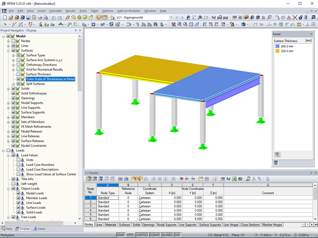
Surface thicknesses can be visualized in the model using various colors.
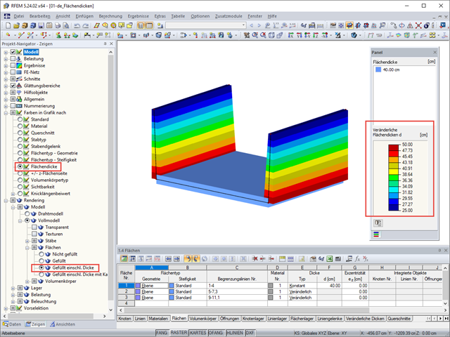
RFEM 5 allows you to show the variable surface thicknesses as a color gradient.
This article describes the design of timber panel walls due to generated horizontal loads.

The design of cold-rolled steel products is defined in EN 1993-1-3. Typical cross-section shapes are channel, C, Z, top hat, and sigma sections. These are cold-rolled steel products made of thin-walled sheet metal that has been cold-formed by roll-forming or bending methods. When designing the ultimate limit states, it is also necessary to ensure that local transverse forces do not lead to compression, crippling of the web, or local buckling in the web of the sections. These effects can be caused by local transverse forces by the flange into the web, as well as by support forces at the supported points. Section 6.1.7 of EN 1993-1-3 specifies in detail how to determine the resistance of the web Rw,Rd under local transverse forces.
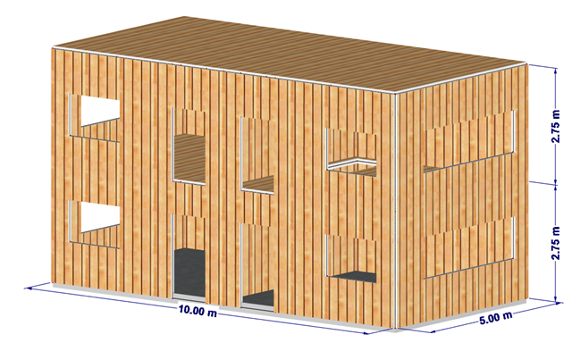
This article shows the effect of the different stiffnesses of the timber panel walls on the floor plan.

The calculation of timber panels is carried out on simplified member or surface structures. This article describes how to determine the required stiffness.

The stiffening of timber structures is usually carried out by means of timber panels. For this purpose, structural components consisting of slabs (chipboard, OSB) are connected with members. Several articles will describe the basics of this construction method and the calculation in the RFEM program. This first article describes the basic determination of the stiffnesses as well as the calculation.

In SHAPE-THIN, the calculation of stiffened buckling panels can be performed according to Section 4.5 of EN 1993-1-5. For stiffened buckling panels, the effective surfaces due to local buckling of the single panels in the plate and in the stiffeners, as well as the effective surfaces from the entire panel buckling of the stiffened entire panel, have to be considered.
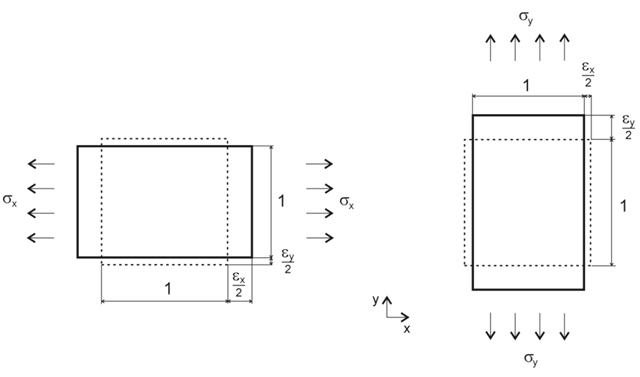
Orthotropic material laws are used wherever materials are arranged according to their loading. Examples include fiber-reinforced plastics, trapezoidal sheets, reinforced concrete, and timber.
![Formula Symbols for Connection Between Chords and Web (Source: [1])](/en/webimage/009346/2418256/01-en-3-png.png?mw=640&hash=7a1bc6e87da6f5aeb6d26a130c6ca3dfb6edb8a4)
In order to ensure the effects of panels, which should act as tensile or compression chords, it is necessary to connect them to the web in a shear-resistant manner. This connection is obtained in a similar way as the shear transfer in the joint between concreting sections by using the interaction between compressive struts and ties. In order to ensure the shear resistance, it must be verified that the compressive strut resistance is given and the tie force can be absorbed by the transverse reinforcement.
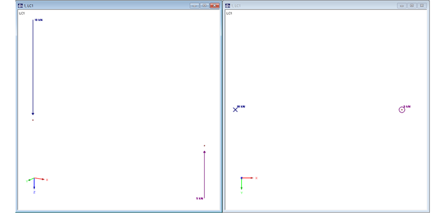
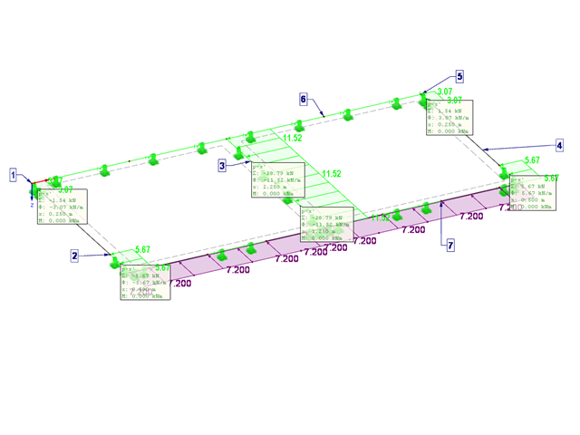
In RFEM, structures can be modeled and analyzed in a spatial environment. The permanent 3D visualization helps you to better understand complex models and to represent the force flux. However, you can switch from a spatial mode to a planar sheet mode in the documentation of a calculation. To do this, you have to describe the spatial calculation of the structure with all the necessary properties on "flat" paper pages for an independent reader. Usually, you try to display the load actions and the corresponding results by using an orthogonal view of the substructure of the entire structure. Obviously, the load symbols depicted in the 3D mode in a view perpendicular to the load become unrecognizable due the missing expansion. In order to still be able to create a clear representation of all information, the corresponding adjustments are available in RFEM.
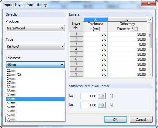
The RF‑LAMINATE library now includes the Kerto‑Q product by the company Metsä Wood. All LVL panels are available, including the characteristic strength parameters.
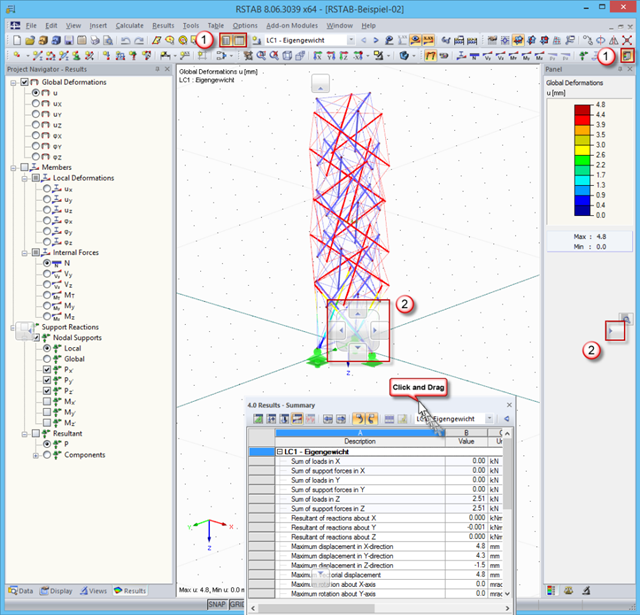
In order to use the working window area optimally for the graphical input of model data or for result evaluation, there are various options for arranging Project Navigator, the table, and the result panel.
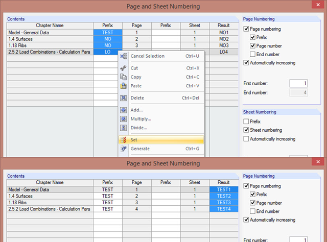
The "Page and Sheet Numbering" dialog box allows you to add a prefix to page and sheet numbering. It can be an abbreviation that specifies by chapter all model data in the numbering (for example, with "MO").
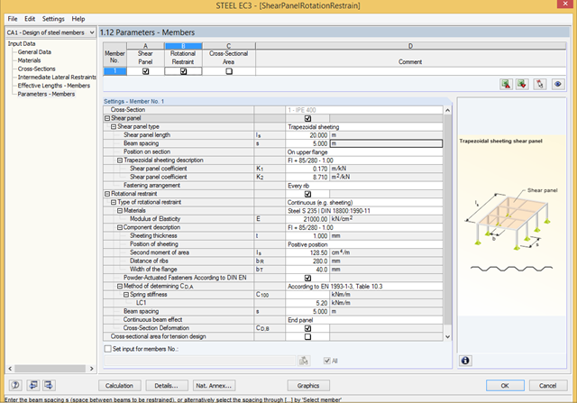
To stabilize the components bearing stability risks, a shear panel and/or a rotational restraint can be defined in RF‑/STEEL EC3. Optionally, trapezoidal sheets, bracings, or individual purlins can be taken into account.

Torsional buckling analysis of transverse and longitudinal stiffeners with open cross-sections is described in DIN EN 1993-1-5, Chapter 9. There is a difference between the simplified method and the precise method, which takes into consideration the warping stiffness of the buckling panel. The simplified method applies Equation 9.3 of DIN EN 1993‑1‑5. If warping stiffness is to be taken into account, either Eq. 9.3 or Eq. 9.4 should be followed. Both design methods are implemented in PLATE-BUCKLING.