49 Results
View Results:
Sort by:

Using the Timber Design add-on, timber column design is possible according to the 2018 NDS standard ASD method. Accurately calculating timber member compressive capacity and adjustment factors is important for safety considerations and design. The following article will verify the maximum critical buckling strength calculated by the Timber Design add-on using step-by-step analytical equations as per the NDS 2018 standard including the compressive adjustment factors, adjusted compressive design value, and final design ratio.

Moment frame design according to AISC 341-16 is now possible in the Steel Design add-on of RFEM 6. The seismic design result is categorized into two sections: member requirements and connection requirements. This article covers the required strength of the connection. An example comparison of the results between RFEM and the AISC Seismic Design Manual [2] is presented.

A new capability within RFEM 6 when designing concrete columns is being able to generate the moment interaction diagram according to the ACI 318-19 [1]. When designing reinforced concrete members, the moment interaction diagram is an essential tool. The moment interaction diagram represents the relationship between the bending moment and axial force at any given point along a reinforced member. Valuable information is shown visually like strength and how the concrete behaves under different loading conditions.
,_Table_22.5.5.1_ACI_318-19.png?mw=640&hash=7e50d54e01238943fe1c691c0aa197d9b2fa8511)
With the most recent ACI 318-19 standard, the long-term relationship to determine the concrete shear resistance, Vc, is redefined. With the new method, the member height, the longitudinal reinforcement ratio, and the normal stress now influence the shear strength, Vc. This article describes the shear design updates, and the application is demonstrated with an example.
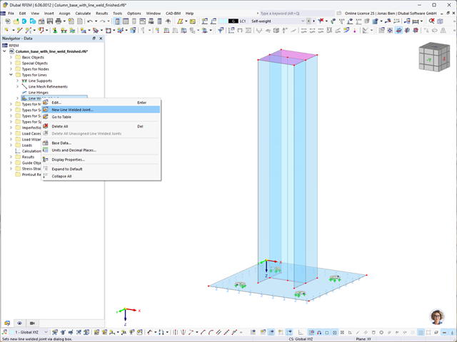
In RFEM 6, it is possible to define line welds between surfaces and calculate the weld stresses using the Stress-Strain Analysis add-on. This article will show you how to do it.

This article discusses the options available for determining the nominal flexural strength, Mnlb for the limit state of local buckling when designing according to the 2020 Aluminum Design Manual.

Steel connections in RFEM 6 are defined as an assembly of components. In the new Steel Joints add-on, universally applicable basic components (plates, welds, auxiliary planes) are available for entering complex connection situations. The methods with which connections can be defined are considered in two previous Knowledge Base articles: “A Novel Approach to Designing Steel Joints in RFEM 6" and “Defining Steel Joint Components Using the Library".

Steel has poor thermal properties in terms of fire resistance. The thermal expansion for increasing temperature is very high compared to that of other building materials, and might result in effects that were not present in the design at normal temperature due to restraint in the component. As temperature increases, steel ductility increases, whereas its strength decreases. Since steel loses 50% of its strength at temperature of 600 °C, it is important to protect components against fire effects. In the case of protected steel components, the fire resistance duration can be increased due to the improved heating behavior.

The reinforced concrete design for fire situations is carried out according to the simplified method based on EN 1992-1-2, Clause 4.2. The "zone method" described in Annex B.2 is used: The cross-section is subdivided into a number of parallel zones of equal thickness, and their temperature-dependent compressive strength is determined. The reduced load-bearing capacity in the event of fire exposure is thus represented by a reduced structural component's cross-section with reduced strengths.

In the case of using slow‑curing concrete (usually for thick components), you can reduce the calculated minimum reinforcement by a factor of 0.85 to apply the load due to restraint, according to EN 1992‑1‑1, Section 7.3.2. However, a precondition for reduction is that the characteristic value of the strength development r = fcm2 / fcm28 does not exceed 0.3. Other key requirements for the application of this reinforcement reduction are specified explicitly in the final planning documents.

The RF‑/STEEL EC3 add-on module can perform the design of fillet welds for all parametric, welded cross-sections of the cross-section library. For this, the option must be activated in the detail settings of the module. As an alternative, you can also use a surface model for the design.
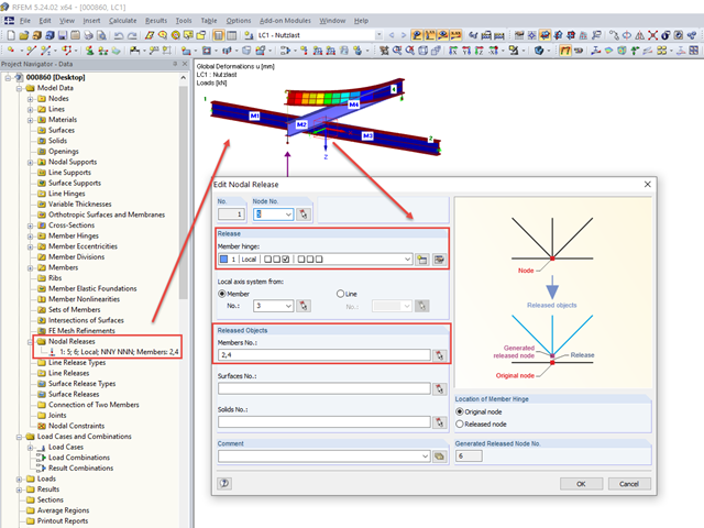
Occasionally, it is necessary to consider in a model that some beams only lie loosely on top of one another without screwing or welding.

In RF-/STEEL EC3, you can optimize a cross-section automatically within the design. To do this, select the corresponding cross-section in Table 1.3 or define variable parameters for a welded cross-section.
.png?mw=640&hash=8fd04a597cecae2e434980ce79fc626815a5d98a)
The Aluminum Design Manual (ADM) 2020 was released in February 2020. The ADM 2020 gives guidance for both the allowable strength design (ASD) and load and resistance factor design (LRFD) for aluminum members to ensure reliability and safety for all aluminum structures. This latest standard was integrated in the RFEM/RSTAB add-on module RF-/ALUMINUM ADM. The text below will highlight the applicable updates relevant to the Dlubal programs.

In the case of open cross-sections, the torsional load is removed mainly via secondary torsion, since the St. Venant torsional stiffness is low compared to the warping stiffness. Therefore, warping stiffeners in the cross-section are particularly interesting for the lateral-torsional buckling analysis, as they can significantly reduce the rotation. For this, end plates or welded stiffeners and sections are suitable.
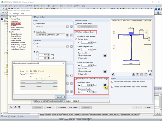
When using interrupted welds between the rail and flange, make sure that the applied weld length does not exceed the length of the rigid load application of the wheel load according to Equation 6.1 in [1].

Concrete on its own is characterized by its compressive strength. An important part of reinforced concrete is reinforcing steel, which contributes to both the compressive and the tension resistance of the concrete. Welded wire fabric is generally located in the tension areas of the beams or surface elements (hollow core ceiling, wall, shell) to transfer the tensile forces induced by external loading.

Table 3.1 of EN 1993‑1‑8:2010‑12 defines the nominal values of the yield strength and the ultimate limit strength of bolts. The bolt classes given here are 4.6, 4.8, 5.6, 5.8, 6.8, 8.8, 10.9. The note for this table states that the National Annex may exclude certain bolt classes. For the NA of Germany, these are the bolt classes 4.8, 5.8, and 6.8.

This technical article deals with the design of structural components and cross-sections of a welded truss girder in the ultimate limit state. Furthermore, the deformation analysis in the serviceability limit state is described.
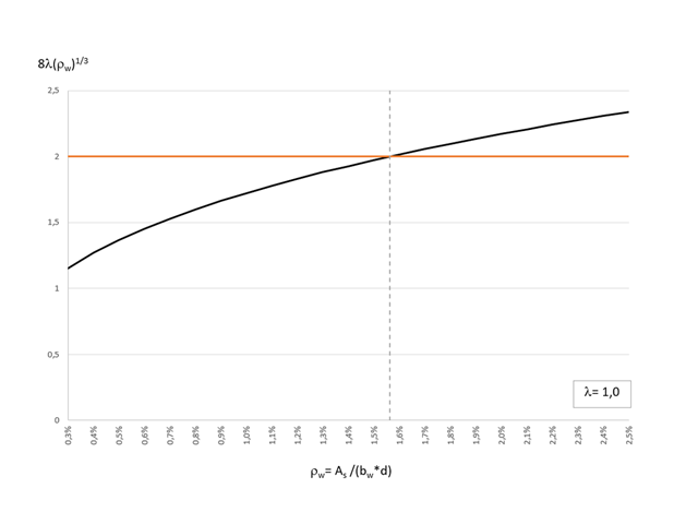
The most recent standard ACI 318‑19 redefines the long-term relation for the determination of the concrete shear resistance Vc. With the new method, the member height, the longitudinal reinforcement ratio, and the normal stress now influence the shear strength, Vc. This article describes the shear design updates, and the application is demonstrated using an example.