35 Results
View Results:
Sort by:

To evaluate whether it is also necessary to consider the second-order analysis in a dynamic calculation, the sensitivity coefficient of interstory drift θ is provided in EN 1998‑1, Sections 2.2.2 and 4.4.2.2. It can be calculated and analyzed using RFEM 6 and RSTAB 9.

For the ultimate limit state design, EN 1998‑1, Sections 2.2.2 and 4.4.2.2 require a calculation considering the second‑order theory (P‑Δ effect). This effect may be neglected only if the interstory drift sensitivity coefficient θ is less than 0.1.

Compliance with building codes, such as Eurocode, is essential to ensure the safety, structural integrity, and sustainability of buildings and structures. Computational Fluid Dynamics (CFD) plays a vital role in this process by simulating fluid behavior, optimizing designs, and helping architects and engineers meet Eurocode requirements related to wind load analysis, natural ventilation, fire safety, and energy efficiency. By integrating CFD into the design process, professionals can create safer, more efficient, and compliant buildings that meet the highest standards of construction and design in Europe.

The events of recent years remind us of the importance of earthquake engineering in seismic regions. For you as an engineer, the design of structures in earthquake-prone areas is a constant trade-off between economic efficiency – the financial possibilities – and structural safety. If a collapse is inevitable, engineers must estimate how it will affect the structure. This article aims to provide you with an option on how to perform this estimation.

When a concrete slab is set upon the top flange, its effect is like a lateral support (composite construction), preventing problems of torsional buckling stability. If there is a negative distribution of the bending moment, the bottom flange is subjected to compression and the top flange is under tension. If the lateral support given by the stiffness of the web is insufficient, the angle between the bottom flange and the web intersection line is variable in this case so that there is a possibility of distortional buckling for the bottom flange.

With the Steel Design add-on, you can design structural steel components in the event of fire using the simple design methods according to Eurocode 3. The component temperature at the time of the design check can be determined automatically according to the temperature-time curves specified in the standard. In addition to considering a cladding for fire protection, it is also possible for you to take account of the beneficial properties of hot-dip galvanization.
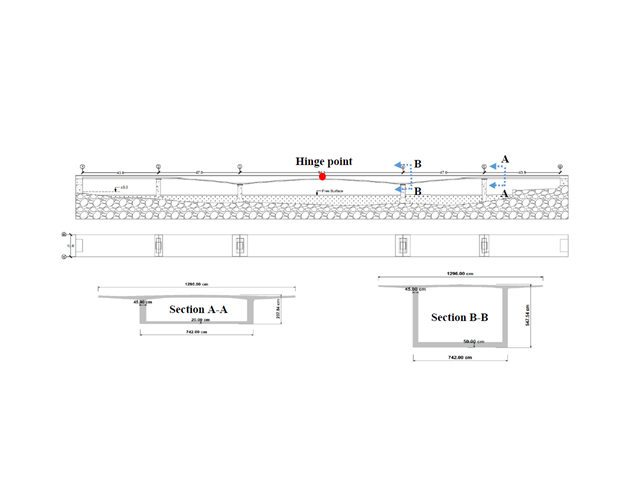
This paper is related to an ongoing project for which a structural digital twin of the Kalix bridge in Sweden is being developed and implemented.

The “Modal Analysis” add-on in RFEM 6 allows you to perform modal analysis of structural systems, thus determining natural vibration values such as natural frequencies, mode shapes, modal masses, and effective modal mass factors. These results can be used for vibration design, as well as for further dynamic analyses (for example, loading by a response spectrum).

Modal analysis is the starting point for the dynamic analysis of structural systems. You can use it to determine natural vibration values such as natural frequencies, mode shapes, modal masses, and effective modal mass factors. This outcome can be used for vibration design, and it can be used for further dynamic analyses (for example, loading by a response spectrum).

Seismic Analysis in RFEM 6 is possible using the modal analysis and the response spectrum analysis add-ons. As a matter of fact, the general concept of the earthquake analysis in RFEM 6 is based on the creation of a load case for the modal analysis and the response spectrum analysis, respectively. The standard groups for these analyses are set in the Standards II tab of the model’s Base Data.

An FE mesh quality display is available in RFEM as a tool for structural analyses of two-dimensional components. It leads to the execution of an internal check of the generated finite elements for defined criteria.
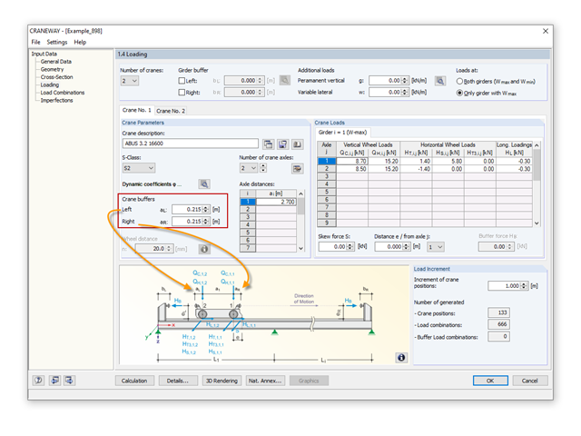
In the event of converting or extending a hall, the building owner may want to add a second or third crane to an existing crane runway. Since the original design usually does not consider other cranes, a common solution is to design a minimum distance between the cranes. This is done via the crane technology settings.

The reinforced concrete design for fire situations is carried out according to the simplified method based on EN 1992-1-2, Clause 4.2. The "zone method" described in Annex B.2 is used: The cross-section is subdivided into a number of parallel zones of equal thickness, and their temperature-dependent compressive strength is determined. The reduced load-bearing capacity in the event of fire exposure is thus represented by a reduced structural component's cross-section with reduced strengths.

The RF-STABILITY add-on module determines any critical load factors, effective lengths, and eigenvectors of RFEM models. Stability analyses can be carried out by various eigenvalue methods, the advantages of which depend on the structural system as well as computer configurations.

Very small torsional moments in the members to be designed often prevent certain design formats. In order to neglect them and still perform the designs, you can define a limit value in RF‑/STEEL EC3 from which torsional shear stresses are taken into account.

The SHAPE‑THIN and SHAPE‑MASSIVE cross-section programs are suitable for determining the cross-section properties of common thin-walled or thick-walled sections. These cross-section properties are also available for further analyses in RSTAB and RFEM.

In EN 1993-1-1, the General Method was introduced as a design format for stability analyses that can be applied to planar systems with arbitrary boundary conditions and variable structural height. The design checks can be performed for loading in the main load-bearing plane and simultaneous compression. The stability cases of lateral-torsional buckling and flexural buckling are analyzed from the main supporting plane; that is, about the weak component axis. Therefore, the issue often arises as to how to design, in this context, flexural buckling in the main load-bearing plane.
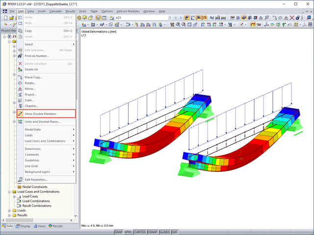
Generally, overlapping members in the model are not desired. To prevent RFEM from deleting an already defined member if another member is placed upon it, select "Allow Double Members" on the "Edit" menu.

- 000487
- Modeling | Structure
- RFEM 5
-
- RF-STEEL 5
- RF-STEEL AISC 5
- RF-STEEL AS 5
- RF-STEEL BS 5
- RF-STEEL CSA 5
- RF-STEEL EC3 5
- RF-STEEL GB 5
- RF-STEEL HK 5
- RF-STEEL IS 5
- RF-STEEL NBR 5
- RF-STEEL NTC-DF 5
- RF-STEEL SANS 5
- RF-STEEL SIA 5
- RF-STEEL SP 5
- RF-ALUMINUM 5
- RF-ALUMINUM ADM 5
- RSTAB 8
- STEEL 8
- STEEL AISC 8
- STEEL AS 8
- STEEL BS 8
- STEEL CSA 8
- STEEL EC3 8
- STEEL GB 8
- STEEL HK 8
- STEEL IS 8
- STEEL NBR 8
- STEEL NTC-DF 8
- STEEL SANS 8
- STEEL SIA 8
- STEEL SP 8
- ALUMINUM 8
- ALUMINUM ADM 8
- Steel Structures
- Process Manufacturing Plants
- Stairway Structures
- Structural Analysis & Design
- Eurocode 3
- ANSI/AISC 360
- SIA 263
- IS 800
- BS 5950-1
- GB 50017
- CSA S16
- AS 4100
- SP 16.13330
- SANS 10162-1
- ABNT NBR 800
- ADM
The support conditions of a beam subjected to bending are essential for its resistance to lateral-torsional buckling. If, for example, a single-span beam is held laterally in the middle of the span, the deflection of the compressed flange can be prevented, and a two-wave eigenmode can be enforced. The critical lateral-torsional buckling moment is increased significantly by this additional measure. In the add-on modules for member design, different types of lateral supports on a member can be defined using the "Intermediate supports" input window.
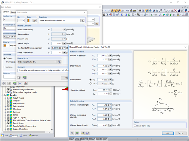
In RFEM, orthotropic plastic analyses using the Tsai‑Wu plasticity criterion have been possible for quite some time now. The hardening modulus Ep,x or Ep,y can be used to consider the hardening of the material during the iterative calculation.
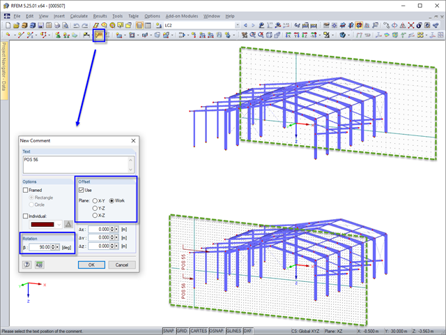
In RFEM and RSTAB, you can add a comment to model objects in the graphic. When inserting a comment, the origin of the current work plane automatically jumps temporarily to the same plane in which the comment is placed. This prevents comments from being accidentally placed very far from the object.
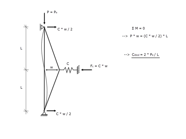
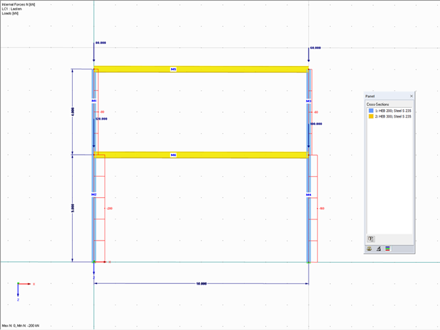
If a member is supported laterally to prevent buckling due to a compressive axial force, it must be ensured that the lateral support is actually able to prevent buckling. Therefore, the aim of this article is to determine the ideal spring stiffness of a lateral support using the Winter model.
With the RF-STABILITY and RSBUCK add-on modules for RFEM and RSTAB, it is possible to perform eigenvalue analyses for member structures in order to determine the effective length factors. The effective length coefficients can then be used for the stability design.

In order to consider inaccuracies regarding the position of masses in a response spectrum analysis, standards for seismic design specify rules that have to be applied in both the simplified and multi-modal response spectrum analyses. These rules describe the following general procedure: The story mass must be shifted by a certain eccentricity, which results in a torsional moment.
The input windows in RF-/STEEL EC3 distinguish between the flexural and lateral-torsional buckling analyses. In the following text, an example will show the parameters for lateral-torsional buckling.
The fundamental requirements of a structural system are (according to the basis of structural design) sufficient ultimate limit state, serviceability, and resistance. Structures must be designed in such a way that no damage occurs due to events such as the impact of a vehicle.

Different methods are available for calculating the deformation in the cracked state. RFEM provides an analytical method according to DIN EN 1992-1-1 7.4.3 and a physical-nonlinear analysis. Both methods have different features and can be more or less suitable depending on the circumstances. This article will give an overview of the two calculation methods.
With RF-FOUNDATION Pro, it is possible to determine the settlements of single foundations and resulting spring stiffnesses of the nodal supports. These spring stiffnesses can be exported into the RFEM model and used for further analyses.
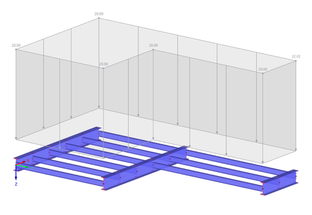
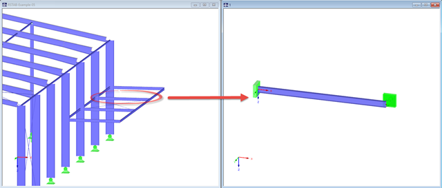
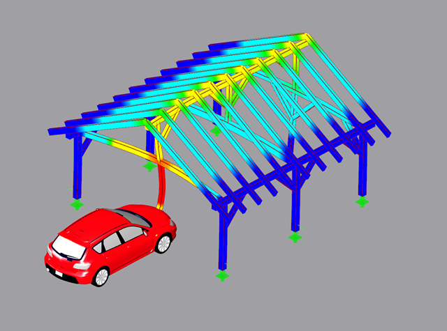
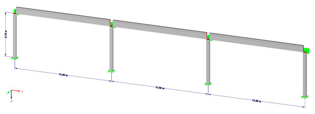
The structural analysis of a girder grillage is usually easy when using computer-aided calculation. There are different options for displaying and analyzing a structure. The conventional kind of structural analysis of components as well as modeling the entire structure are among the possibilities.
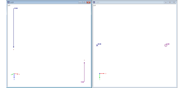
In RFEM, structures can be modeled and analyzed in a spatial environment. The permanent 3D visualization helps you to better understand complex models and to represent the force flux. However, you can switch from a spatial mode to a planar sheet mode in the documentation of a calculation. To do this, you have to describe the spatial calculation of the structure with all the necessary properties on "flat" paper pages for an independent reader. Usually, you try to display the load actions and the corresponding results by using an orthogonal view of the substructure of the entire structure. Obviously, the load symbols depicted in the 3D mode in a view perpendicular to the load become unrecognizable due the missing expansion. In order to still be able to create a clear representation of all information, the corresponding adjustments are available in RFEM.