27 Results
View Results:
Sort by:

A new capability within RFEM 6 when designing concrete columns is being able to generate the moment interaction diagram according to the ACI 318-19 [1]. When designing reinforced concrete members, the moment interaction diagram is an essential tool. The moment interaction diagram represents the relationship between the bending moment and axial force at any given point along a reinforced member. Valuable information is shown visually like strength and how the concrete behaves under different loading conditions.

In accordance with Sect. 6.6.3.1.1 and Clause 10.14.1.2 of ACI 318-19 and CSA A23.3-19, respectively, RFEM effectively takes into consideration concrete member and surface stiffness reduction for various element types. Available selection types include cracked and uncracked walls, flat plates and slabs, beams, and columns. The multiplier factors available within the program are taken directly from Table 6.6.3.1.1(a) and Table 10.14.1.2.

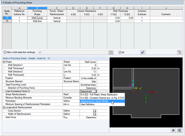
The punching shear design, in line with EN 1992-1-1, should be performed for slabs with a concentrated load or reaction. The node where the design of punching shear resistance is performed (that is, where there is a punching problem) is called a node of punching shear. The concentrated load at these nodes can be introduced by columns, concentrated force, or nodal supports. The end of the linear load introduction on slabs is also regarded as a concentrated load and therefore, the shear resistance at wall ends, wall corners, and ends or corners of line loads and line supports should be controlled as well.

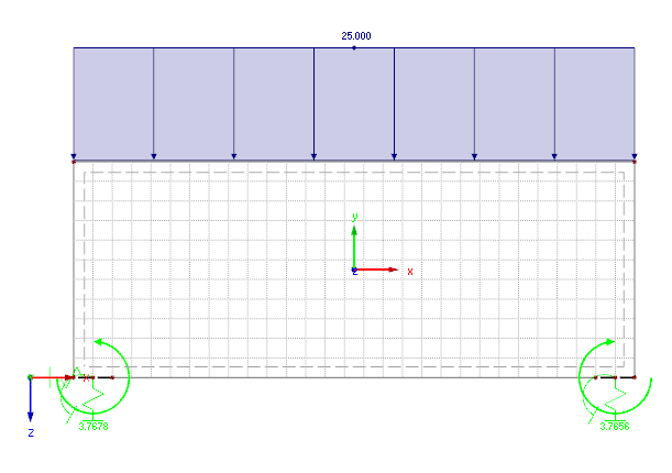
This article describes how a flat slab of a residential building is modeled in RFEM 6 and designed according to Eurocode 2. The plate is 24 cm thick and is supported by 45/45/300 cm columns at distances of 6.75 m in both the X and Y directions (Image 1). The columns are modeled as elastic nodal supports by determining the spring stiffness based on the boundary conditions (Image 2). C35/45 concrete and B 500 S (A) reinforcing steel are selected as the materials for the design.

This article deals with rectilinear elements of which the cross-section is subjected to axial compressive force. The purpose of this article is to show how very many parameters defined in the Eurocodes for concrete column calculation are considered in the RFEM 5 structural analysis software.

This article compares the design to the one in the referenced article: Design of Concrete Columns Subjected to Axial Compression with RF-CONCRETE Members. It is, therefore, about taking exactly the same theoretical application carried out in RF-CONCRETE Members and reproducing it in RF-CONCRETE Columns. Thus, the objective is to compare the different input parameters and the results obtained by the two add-on modules for the design of column-like concrete members.

In RF‑/FOUNDATION Pro, the available reinforcing steel diameters can be adjusted by the user. The adjustment of the available rebar diameters works similarly to the same function in the RF‑/CONCRETE (Members) and RF‑/CONCRETE Columns add‑on modules.

In RF‑/CONCRETE Columns, different methods are available for defining the minimum longitudinal reinforcement. The minimum reinforcement can be selected according to the design standard used and/or specified by the user.

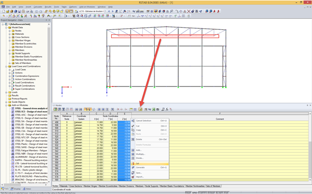
The same structures are often needed in several projects, such as the purlin with columns and braces in this example. The dimensions can be changed directly in RFEM or RSTAB by shifting the nodes.

This article deals with elements concerning which the cross-section is subjected simultaneously to a bending moment, a shear force, and an axial compressive or tensile force. However, in our example we will not include loading due to shear force.

In accordance with Sec. 6.6.3.1.1 and Sec. 10.14.1.2 of ACI 318-14 and CSA A23.3-14, respectively, RFEM effectively takes into consideration concrete member and surface stiffness reduction for various element types. Available selection types include cracked and uncracked walls, flat plates and slabs, beams, and columns. The multiplier factors available within the program are taken directly from Table 6.6.3.1.1(a) and Table 10.14.1.2.
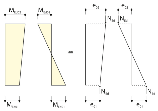
When calculating the internal forces for the buckling analysis with the method based on nominal curvature in RF‑CONCRETE Columns, the required eccentricities have to be determined.

RFEM and RSTAB offer different options to model bored piles. One option is to display bored piles as single-valued supports or hinged columns. Another option is realistic modeling while taking the soil into account by means of applying a member elastic foundation. The two following examples will describe it in detail. However, pile base resistance, skin friction, and soil layers are not considered in this technical article.

When designing steel columns or steel beams, it is usually necessary to carry out cross-section design and stability analysis. While the cross-section design can usually be performed without giving further details, the stability analysis requires further user-defined entries. To a certain extent, the member is cut out of the structure; therefore, the support conditions have to be specified. This is particularly important when determining the ideal elastic critical moment Mcr. Furthermore, it is necessary to define the correct effective lengths Lcr. These are required for the internal calculation of slenderness ratios.
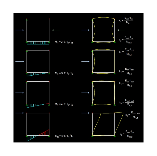
Effective lengths for columns can be determined automatically with RF-/CONCRETE Columns. This article describes which entries are necessary and how the calculation of the effective lengths is performed.
.png?mw=640&hash=5852c5c8a1cdb9f021a168d75c0a0466fb430ef7)
Lattice towers represent typical applications in steel construction. Examples of this special type of truss structure are antenna and overhead line towers, as well as columns for wind power stations, cable cars, and supporting frame constructions. The modeling can be done individually in RFEM and RSTAB by entering various tower elements. Furthermore, you can use different copy functions and parameterized input options. However, this procedure normally requires considerable effort. It is more convenient to model such structures using prefabricated catalog elements provided by the Block Manager. These elements are automatically stored in the database during program installation. Thus, you can use tower segments, platforms, antenna brackets, cable ducts, and so on as parameterized building blocks for generating diverse tower structures.
In the case of plate structures, it is always necessary to consider realistic definition support conditions. Depending on the way of defining the flexibility of the supports, clear differences may occur in the results.
![System and Loading According to [1]](/en/webimage/009455/2418877/01-en-png.png?mw=640&hash=c76563b459152b19c98197ea6ba342be89d9a5bc)
The product range of Dlubal Software contains various modules for the design of steel and timber connections. The RF-/JOINTS Steel – Column Base add-on module allows you to analyze footings of hinged or restrained steel column bases. The fastener selection, foundation geometry, and material quality are crucial for the cost-effective and safe design of the column base.
The RF-PUNCH Pro add-on module allows you to perform punching shear designs according to EN 1992‑1‑1 [1]. In addition to the design checks of single columns, wall ends and wall corners can be analyzed in RF‑PUNCH Pro. At this point, I would also like to reference a previous article about RF‑PUNCH Pro, which explains how to determine punching load on wall ends and wall corners.
![System and Loading According to [1]](/en/webimage/009634/2419765/01-en-png-png.png?mw=640&hash=5e657e3feb5c1bb6d21727468dd85d91e1c9f29f)
A structural analysis does not only determine and design internal forces and deformations. It also ensures that the forces and moments in a structure are generated in a reliable way and applied to the foundation. Dlubal Software provides a wide range of products for the structural analysis and design of steel and timber connections. The RF-/JOINTS Steel – Column Base add-on module allows you to design footings of hinged and restrained column bases. The design can be performed for column base plates with or without stiffeners.
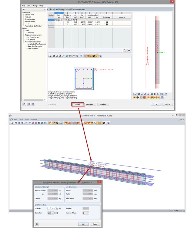
The new options for the graphical display of reinforcements that were implemented in RF‑CONCRETE Members and CONCRETE are now also available in RF‑/CONCRETE Columns.

For structural components consisting of slabs, it is necessary to perform shear design on the locations with concentrated load introduction, applying the punching shear design rules according to Sect. 6.4 of EN 1992‑1‑1 [1]. The concentrated load introduction is present on the individual locations; for example, by columns, concentrated load, or nodal supports. In addition, the end of linear load introduction on slabs is also regarded as concentrated load introduction. For example, this includes wall ends, wall corners, and ends or corners of line loads and line supports. You can perform the punching shear design for floor slabs or foundations, considering the existing available plate topology about the designed node of punching shear. The punching shear design according to EN 1992‑1‑1 checks that the acting shear force vEd does not exceed the resistance vRd.
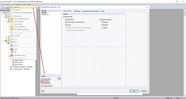
In the global selection of the printout report, you can select in the lower "Display" section whether you want to create a table of contents. The table of contents of the printout report usually requires too much space when displayed in one column.

The national parameters of EN 1992‑1‑1 for each country can be exported from RF‑/CONCRETE, RF‑/CONCRETE Columns, and RF‑/FOUNDATION Pro. To do this, there are interfaces with MS Excel, OpenOffice, and CSV. By exporting the national parameters, you can edit them in (for example) MS Excel, and display possible differences between the individual National Annexes clearly (see the image).
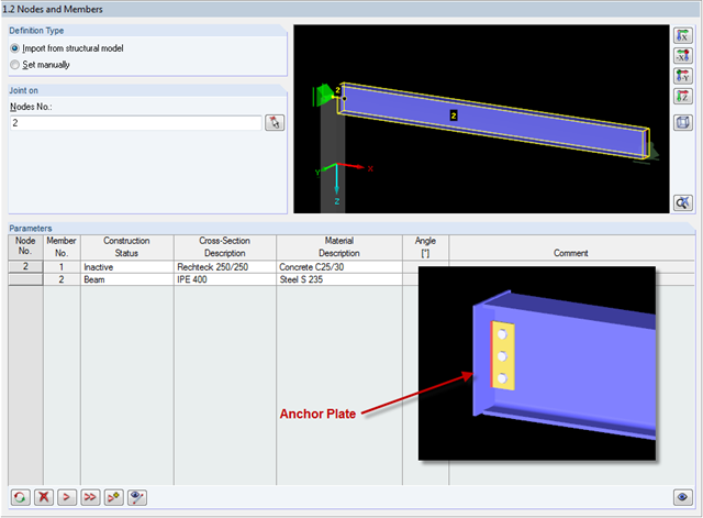
In RF-/JOINTS Steel - Pinned, it is possible to design connections without a supporting structure (for example, columns). In this case, the beam is connected to an anchor plate. How is this kind of connection defined?
In addition to the standard functions, the input tables of the main program have block functions. With these functions, you can edit the data in the selected rows and columns of the table in one step.
In RFEM and RSTAB, the internal forces of individual load combinations are determined according to the second-order analysis by default. If you use the RF‑CONCRETE add‑on module for stability analysis of reinforced concrete columns, you can change the calculation method of LCs to the linear static analysis, since the effects of the second‑order analysis are already considered in the calculation according to the model column method in RF‑CONCRETE Columns (nominal curvature method).