136 Results
View Results:
Sort by:

The three types of moment frames (Ordinary, Intermediate, Special) are available in the Steel Design add-on of RFEM 6. The seismic design result according to AISC 341-22 is categorized into two sections: member requirements and connection requirements.

The National Building Code of Canada (NBC) 2020 Article 4.1.8.7 provides a clear procedure for earthquake methods of analysis. The more advanced method, the Dynamic Analysis Procedure in Article 4.1.8.12, should be used for all structure types except those that meet the criteria set forth in 4.1.8.7. The more simplistic method, the Equivalent Static Force Procedure (ESFP) in Article 4.1.8.11, can be used for all other structures.

This article explains how the calculation in the initial stiffness analysis in Steel Joints works.

The three types of moment frames (Ordinary, Intermediate, Special) are available in the Steel Design add-on of RFEM 6. The seismic design result according to AISC 341-16 is categorized into two sections: member requirements and connection requirements.

Moment frame design according to AISC 341-16 is now possible in the Steel Design add-on of RFEM 6. The seismic design result is categorized into two sections: member requirements and connection requirements. This article covers the required strength of the connection. An example comparison of the results between RFEM and the AISC Seismic Design Manual [2] is presented.

The design of an Ordinary Concentrically Braced Frame (OCBF) and a Special Concentrically Braced Frame (SCBF) can be carried out in the Steel Design add-on of RFEM 6. The seismic design result according to AISC 341-16 and 341-22 is categorized into two sections: Member Requirements and Connection Requirements.

Plate girder is an economical choice for long spans construction. I-section steel plate girder typically has a deep web to maximize its shear capacity and flange separation, yet thin web to minimize the self-weight. Due to its large height-to-thickness (h/tw) ratio, transverse stiffeners may be required to stiffen the slender web.

In this article, a lap joint of a ZL purlin on a monopitch roof is modeled and designed using the Steel Joints add-on, and compared with the load-bearing capacity table of the manufacturer.

Steel connections in RFEM 6 can be created by simply entering predefined components in the Steel Joints add-on. The collection of these components is constantly being improved to make your work even easier even when modeling steel connections. In this article, the connection plate component is introduced as a component recently added to the add-on's library.
,_Table_22.5.5.1_ACI_318-19.png?mw=640&hash=7e50d54e01238943fe1c691c0aa197d9b2fa8511)
With the most recent ACI 318-19 standard, the long-term relationship to determine the concrete shear resistance, Vc, is redefined. With the new method, the member height, the longitudinal reinforcement ratio, and the normal stress now influence the shear strength, Vc. This article describes the shear design updates, and the application is demonstrated with an example.

The properties of the connection between a reinforced concrete slab and a masonry wall can be correctly considered in the modeling using a special line hinge that is available in RFEM 6. This article will show you how to define this type of hinge using a practical example.

This article will show you how to properly consider the connection between surfaces that touch each other on one line with the help of line hinges in RFEM 6.

The optimal scenario in which punching shear design according to ACI 318-19 [1] or CSA A23.3:19 [2] should be utilized is when a slab is experiencing a high concentration of loading or reaction forces occurring at one single node. In RFEM 6, the node in which punching shear is an issue is referred to as a punching shear node. The causes of these high concentration of forces can be introduced by a column, concentrated force, or nodal support. Connecting walls can also cause these concentrated loads at wall ends, corners, and ends of line loads and supports.

This article shows you the internal forces and displacements of a continuous beam calculated both with and without consideration of shear stiffness.

You can model and analyze masonry structures in RFEM 6 with the Masonry Design add-on that employs the finite element method for the design. Complex masonry structures can be modeled, and static and dynamic analysis can be performed, given that a nonlinear material model is implemented in the program to display the load-bearing behavior of masonry and the different failure mechanisms. You can enter and model masonry structures directly in RFEM 6 and combine the masonry material model with all common RFEM add-ons. In other words, you can design entire building models in connection with masonry.

The advantage of the RFEM 6 Steel Joints add-on is that you can analyze steel connections using an FE model for which the modeling runs fully automatically in the background. The input of the steel joint components that control the modeling can be done by defining the components manually, or by using the available templates in the library. The latter method is included in a previous Knowledge Base article titled “Defining Steel Joint Components Using the Library". The definition of parameters for the design of steel joints is the topic of the Knowledge Base article “Designing Steel Joints in RFEM 6".

Steel connections in RFEM 6 are defined as an assembly of components. In the new Steel Joints add-on, universally applicable basic components (plates, welds, auxiliary planes) are available for entering complex connection situations. The methods with which connections can be defined are considered in two previous Knowledge Base articles: “A Novel Approach to Designing Steel Joints in RFEM 6" and “Defining Steel Joint Components Using the Library".

You can use the Steel Joints add-on in RFEM 6 to create and analyze steel connections using an FE model. You can control the modeling of the connections via a simple and familiar input of components. Steel joint components can be defined manually, or by using the available templates in the library. The former method is included in a previous Knowledge Base article titled “A Novel Approach to Designing Steel Joints in RFEM 6". This article will focus on the latter method; that is, it will show you how to define steel joint components using the available templates in the program’s library.

According to EN 1992-1-1 [1], a beam is a member of which the span is no less than 3 times the overall section depth. Otherwise, the structural element should be considered as a deep beam. The behavior of deep beams (that is, beams with a span less than 3 times the section depth) is different from the behavior of normal beams (that is, beams with a span that is 3 times greater than the section depth).
However, designing deep beams is often necessary when analyzing the structural components of reinforced concrete structures, since they are used for window and door lintels, upstand and downstand beams, the connection between split-level slabs, and frame systems.

In RFEM 6, seismic analysis can be done by using the Modal Analysis and the Response Spectrum Analysis add-ons. Once the spectral analysis has been performed, it is possible to use the Building Model add-on to display story actions, interstory drifts, and forces in shear walls.

The punching shear design, in line with EN 1992-1-1, should be performed for slabs with a concentrated load or reaction. The node where the design of punching shear resistance is performed (that is, where there is a punching problem) is called a node of punching shear. The concentrated load at these nodes can be introduced by columns, concentrated force, or nodal supports. The end of the linear load introduction on slabs is also regarded as a concentrated load and therefore, the shear resistance at wall ends, wall corners, and ends or corners of line loads and line supports should be controlled as well.

One of the innovations in RFEM 6 is the approach to designing steel connections. In contrast to RFEM 5, where the design of steel joints is based on an analytical solution, the Steel Joints add-on in RFEM 6 offers an FE solution for steel connections.

RF-CONCRETE Members also includes the design of a shear joint. In order to perform this design, you should select the "Shear joint available" check box in Window 1.6, Shear Joint tab.

In CRANEWAY, the action of a rail as "statically effective" or "statically ineffective" is defined under "Rail‑Flange Connection" in the Details dialog box. This setting controls the calculation of the load introduction length according to EN 1993-6, Tab. 5.1.

An elastic foundation can be applied to a member. Thus, the influence of the soil is usually included in the modeling. Member elastic foundations can only be defined for the "Beam" member type.

Cross-section properties in RFEM and RSTAB include different types of shear areas. This technical article explains the calculation and meaning of various values.

Very small torsional moments in the members to be designed often prevent certain design formats. In order to neglect them and still perform the designs, you can define a limit value in RF‑/STEEL EC3 from which torsional shear stresses are taken into account.
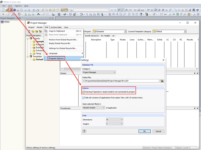
Warning Regarding Connection to Project
---
When opening a model immediately after opening the program, there is a message window asking if you want to create a new project for the model in the Project Manager.

To simulate a support clearance in a connection between members, you can use the "Diagram" function for member hinges. To use this function, first define the relevant degree of freedom as release. Then, you can select the "Diagram" function from the drop‑down list.
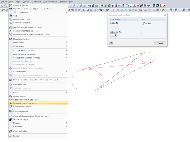
Various tools for modeling are available in RFEM. The modeling functions allow you to represent complex structures quickly and efficiently in the program. The connection of two circles or arcs, for example, can be generated with the "Tangent to Circles or Arcs" function.