31 Results
View Results:
Sort by:

In this article, the calculation of a timber panel wall with the beam panel thickness type is compared with a manual calculation.

Moment frame design according to AISC 341-16 is now possible in the Steel Design add-on of RFEM 6. The seismic design result is categorized into two sections: member requirements and connection requirements. This article covers the required strength of the connection. An example comparison of the results between RFEM and the AISC Seismic Design Manual [2] is presented.

When calculating regular structures, data input is often not complicated but time-consuming. Input automation can save valuable time. The task described in the present article is to consider the stories of a house as single construction stages. Data is entered using a C# program so that the user does not have to enter the elements of the individual floors manually.

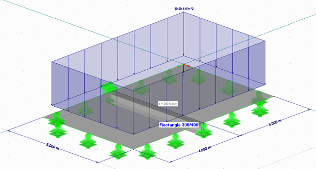
This article discusses the options available for determining the nominal flexural strength, Mnlb for the limit state of local buckling when designing according to the 2020 Aluminum Design Manual.

The advantage of the RFEM 6 Steel Joints add-on is that you can analyze steel connections using an FE model for which the modeling runs fully automatically in the background. The input of the steel joint components that control the modeling can be done by defining the components manually, or by using the available templates in the library. The latter method is included in a previous Knowledge Base article titled “Defining Steel Joint Components Using the Library". The definition of parameters for the design of steel joints is the topic of the Knowledge Base article “Designing Steel Joints in RFEM 6".

You can use the Steel Joints add-on in RFEM 6 to create and analyze steel connections using an FE model. You can control the modeling of the connections via a simple and familiar input of components. Steel joint components can be defined manually, or by using the available templates in the library. The former method is included in a previous Knowledge Base article titled “A Novel Approach to Designing Steel Joints in RFEM 6". This article will focus on the latter method; that is, it will show you how to define steel joint components using the available templates in the program’s library.

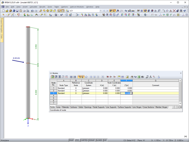
The stability checks for the equivalent member design according to EN 1993-1-1, AISC 360, CSA S16, and other international standards require consideration of the design length (that is, the effective length of the members). In RFEM 6, it is possible to determine the effective length manually by assigning nodal supports and effective length factors or, on the other hand, by importing it from the stability analysis. Both options will be demonstrated in this article by determining the effective length of the framed column in Image 1.

The dialog box for editing load or result combinations is a non-modal dialog box. This means that after you open this dialog box, you can edit the combinations outside the dialog box as well. For manually defining or editing a combination, a separate dialog box can be opened parallel to the "Edit load cases and combinations" dialog box.
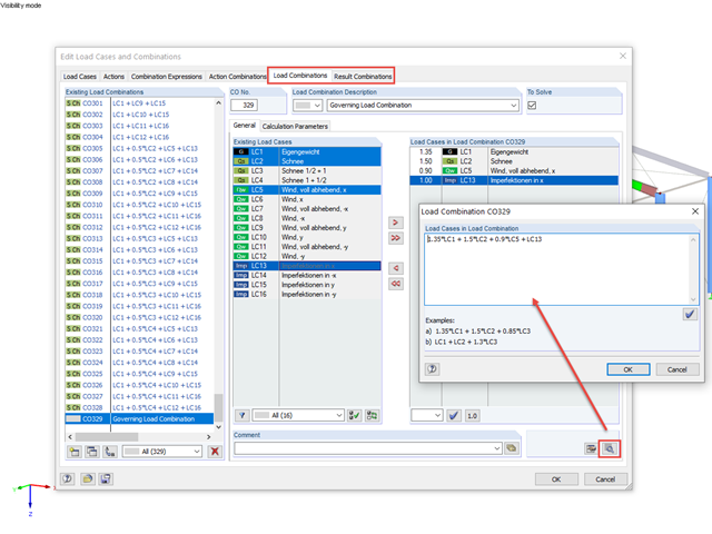
RFEM and RSTAB offer the possibility to edit or check the combinations directly by entering text.

In the default setting, the cross-section class for each member and load case is determined automatically in the design modules. In the input window of the cross sections, however, the user can also specify the cross-section class manually; for example, if local buckling is excluded by the design.

In RFEM, surfaces are automatically connected if they have common boundary lines. If the definition line of a surface is lying in another surface, the line is automatically integrated into the surface, provided that it is a planar surface. For quadrangle surfaces, however, automatic object detection would be relatively time-consuming. For this reason, the corresponding function is deactivated. The integrated objects must be specified manually.
Model and load objects can be defined graphically or in tables, or they can be created using parameters (see the manual). With this parameterized input, you can also access the cells of certain tables of the program. In this way, it is possible to link a load parameter with a model data parameter, for example. The reference is created by the $ sign.

The RF‑/STEEL EC3 add-on module automatically transfers the buckling line to be used for the flexural buckling analysis for a cross-section from the cross-section properties. The assignment of the buckling line can be adjusted manually in the module input for general cross-sections in particular, as well as for special cases.
.png?mw=640&hash=8fd04a597cecae2e434980ce79fc626815a5d98a)
The Aluminum Design Manual (ADM) 2020 was released in February 2020. The ADM 2020 gives guidance for both the allowable strength design (ASD) and load and resistance factor design (LRFD) for aluminum members to ensure reliability and safety for all aluminum structures. This latest standard was integrated in the RFEM/RSTAB add-on module RF-/ALUMINUM ADM. The text below will highlight the applicable updates relevant to the Dlubal programs.
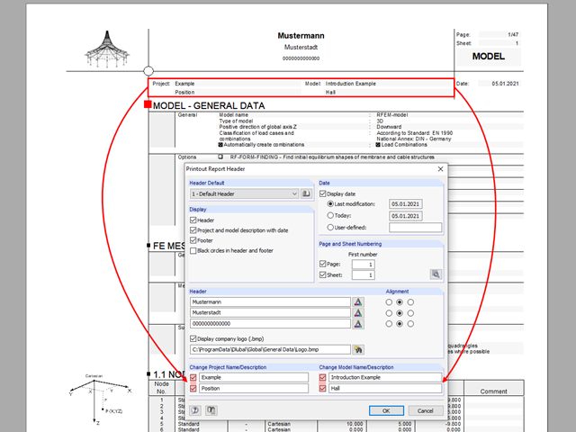
The name of the project/model from the General Data is shown in the header of the printout report by default. In RFEM 5 and RSTAB 8, the model name can be changed manually in the printout report independently of the actual name.

In the RF‑/HSS add‑on module, you can analyze the connections for nodes at which hollow sections join. RF‑/HSS performs the ultimate limit state designs according to EN 1993‑1‑8:2005.
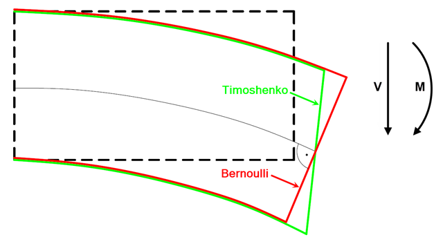
In current literature, the formulas used to determine internal forces and deformations manually are usually specified without considering the shear deformation. The deformations resulting from shear force are often underestimated in timber construction in particular.
When performing control calculations and comparing the internal forces and the resulting required reinforcement of downstand beams, large differences can occur. Although the same load assumptions and spans are applied, some programs or the manual calculation display very different internal forces compared to the FEA model. The differences already occur in the case of the centric member and without considering the internal forces' components from the possible effective slab widths.

RFEM offers the following options to design a pinned end plate connection. First, there is the option in RF-JOINTS Steel - Pinned to enter the corresponding parameters quickly and easily to receive a documented analysis, including graphics. It is also possible to model such a connection individually in RFEM and then to evaluate or manually design the results. In the following example, the particularities of this modeling will be explained and the shear forces of the bolts will be compared to the corresponding results from RF-JOINTS Steel - Pinned.
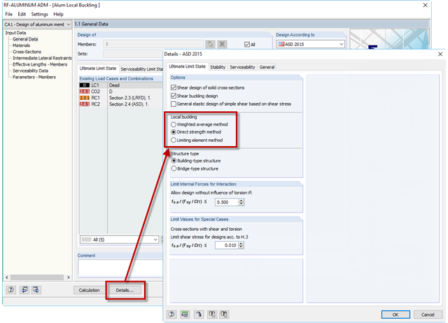
If an aluminum member section is comprised of slender elements, failure can occur due to the local buckling of the flanges or webs before the member can reach full strength. In the add-on module RF-/ALUMINUM ADM, there are now three options for determining the nominal flexural strength for the limit state of local buckling, Mnlb, from Section F.3 in the 2015 Aluminum Design Manual. The three options include sections F.3.1 Weighted Average Method, F.3.2 Direct Strength Method, and F.3.3 Limiting Element Method.
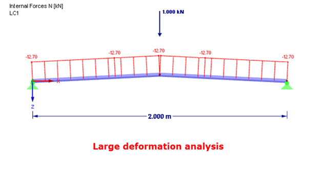
In the case of a post-critical failure, a substantial change occurs in the geometry of a structure. After reaching the instability of the equilibrium, a stable, strength position is reached again. The post-critical analysis requires an experimental approach. It is necessary to manually load the structure in increments, step by step.

If you want to connect members tangentially to a curved member or a curved surface in RFEM, it is necessary to define the member rotation of the connected members. In order to avoid manual determination, you can display the center point of the curved line and place a node on it. Then, you can select the "Member Rotation via Help node" option and specify the relevant help nodes. Thus, the members are rotated automatically in the defined plane (x-z in our example) and the top edge of the rotated cross-section is parallel to the tangent of the curved line.
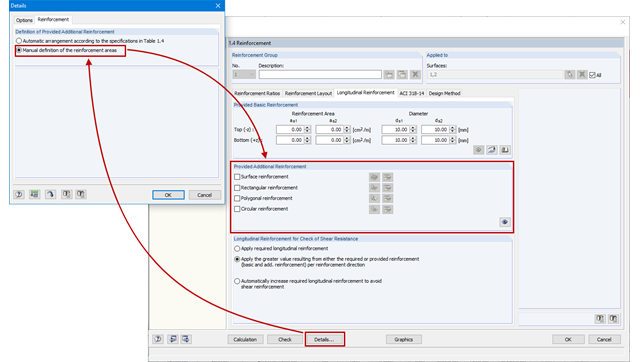
As an alternative to the conventional automatic arrangement of surface reinforcement in RF-CONCRETE Surfaces, it is also possible to set it according to the individual requirements. This is advantageous for the creation of reinforcement drawings, for example, as the reinforcement areas can be clearly defined and dimensioned.
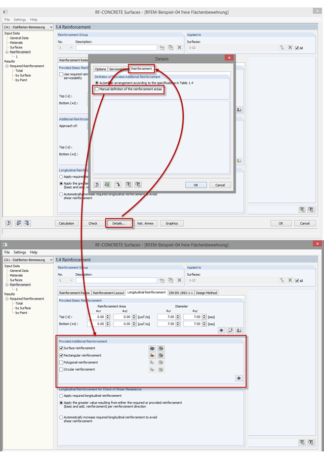
As of program version RFEM 5.06, you can not only perform the automatic arrangement of an additional reinforcement, but also define the surface reinforcement manually. In addition to the uniformly distributed basic reinforcement, you can define various surface reinforcements (per surface; rectangular, circular, or polygonal).
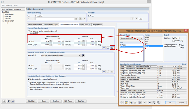
In RF-CONCRETE Surfaces, the reinforcement areas of the mesh reinforcement for basic and additional reinforcement are not entered manually, but you can select them in the library. Therefore, various product ranges are available (for example, from Germany, Austria, and the United States).
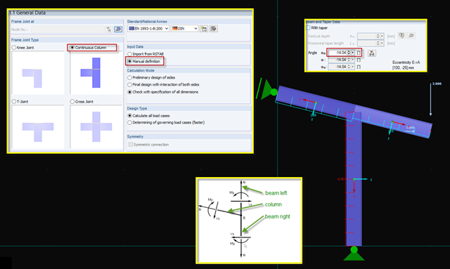
Since no automated frame joints of the "continuous beam" type are included in RF‑/FRAME‑JOINT Pro, you can use another option for designing this type. Designing this kind of beam combination is possible using manual definition and the "Continuous Column" type.
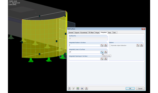
RFEM facilitates modeling by the automatic integration of objects into surfaces. However, it is impossible to integrate the objects automatically in the case of curved surfaces. For manual integration, select the relevant surfaces and click the "Edit Surfaces" option in the shortcut menu; then, in the "Integrated" tab, you can integrate the relevant objects using the "Select" function. This way, you can avoid error messages caused by non‑integrated objects when starting the calculation.
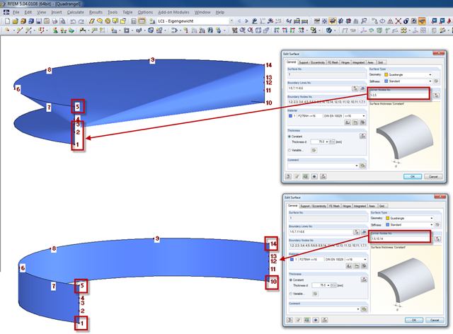
When creating a quadrangular surface, RFEM can automatically detect the four corner nodes. For more complex structures, it can happen that the optimal corner nodes are not found. Manually entering the four corner nodes can lead to a better result, in this case.
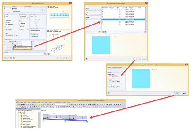
In addition to manually entering values, you can enter line loads in the "Member Load" dialog box using the "Multi-Layer Composition" function. This is a library that contains the compositions of several layers for applying loads. You can freely specify the layer structure using the parameters of description, thickness, density, or surface load, and comment for each layer.
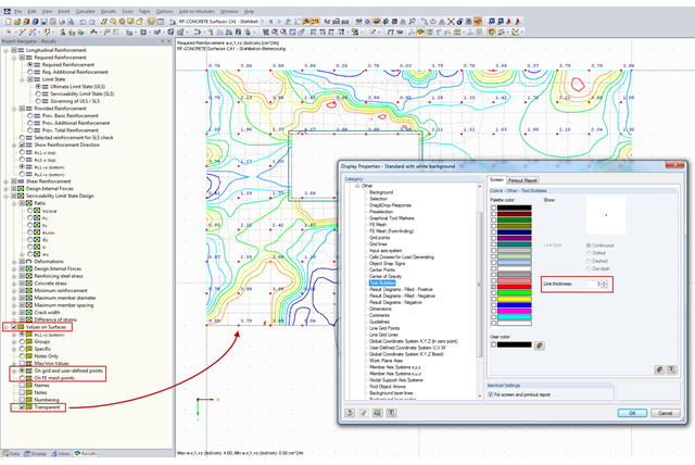
You can document the results of RF‑CONCRETE Surfaces graphically in the printout report. To do this, the "Values on Surfaces" setting is often selected in the Results Navigator of RF‑CONCRETE Surfaces. A text bubble including a result value is displayed, and depending on the settings in the Results Navigator, it can be displayed on the surface grid points, manually defined points, or in FE mesh points.