27 Results
View Results:
Sort by:

In RFEM 6, the results for the FE mesh nodes are determined using the finite element method. For the distribution of internal forces, deformations, and stresses to be continuous, these nodal values are smoothed through an interpolation process. This article will introduce and compare the different types of smoothing that you can use for this purpose.
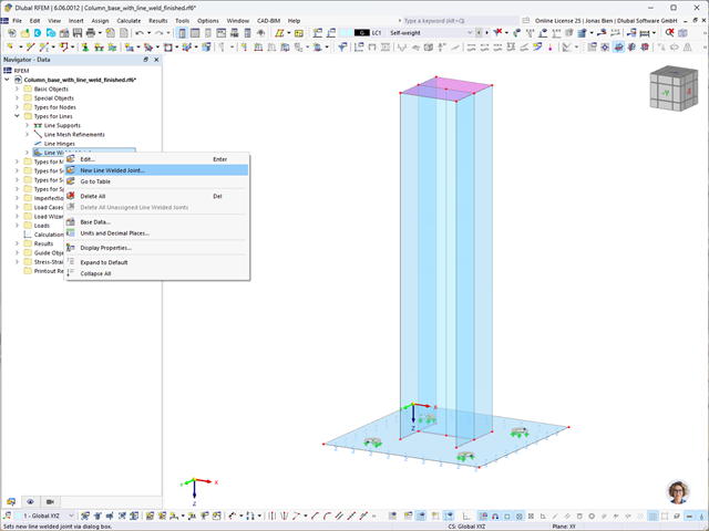
In RFEM 6, it is possible to define line welds between surfaces and calculate the weld stresses using the Stress-Strain Analysis add-on. This article will show you how to do it.
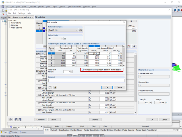
The limit stresses in RF‑/STEEL can be user-defined for each thickness range.

Very small torsional moments in the members to be designed often prevent certain design formats. In order to neglect them and still perform the designs, you can define a limit value in RF‑/STEEL EC3 from which torsional shear stresses are taken into account.

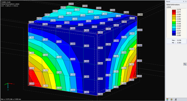
Each solid has a local coordinate system. The stresses and strains are also related to this local axis system.
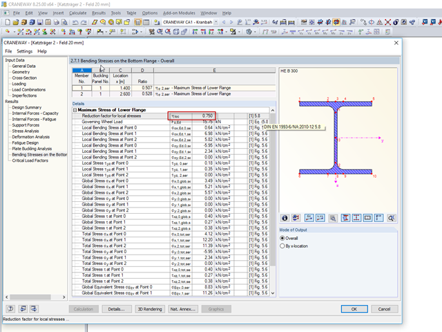
In CRANEWAY 8, you can design suspension cranes according to EN 1993-6. For the design, it is necessary to determine the local bending stresses in the lower flange due to wheel loads according to EN 1993‑6, Clause 5.8.
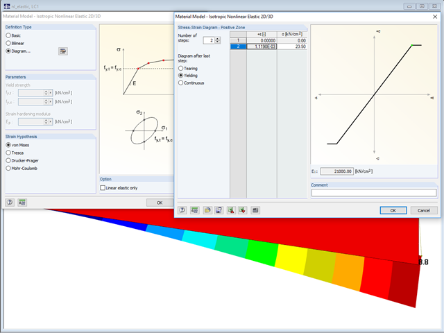
In the "Material Model - Isotropic Nonlinear Elastic" window, you can select the yield laws according to the von Mises, Tresca, Drucker-Prager, and Mohr-Coulomb yield rules. This makes it possible to describe the elasto-plastic material behavior. The yield function depends on the principal stresses or the invariants of a stress tensor. The criteria apply to 2D and 3D material models.
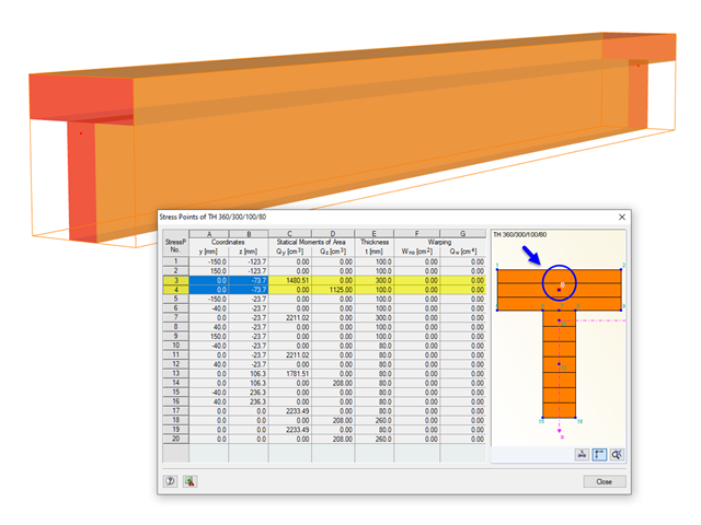
The stresses in the cross‑section of the member are calculated in the stress points. These points are set at locations in the cross‑section where extreme values for the stresses due to the loading types can occur in the material.
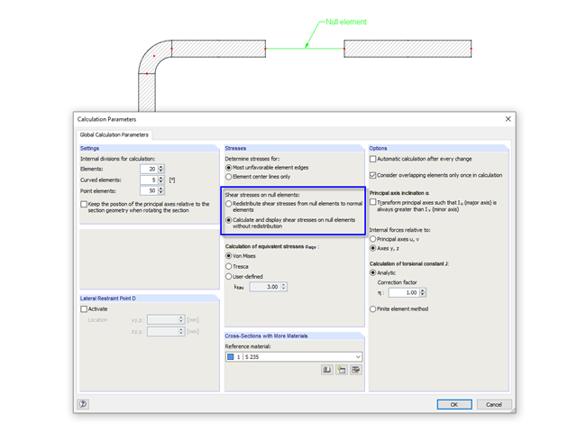
In cross‑sections created in SHAPE‑THIN, the openings, such as bolt holes, can be modeled by using the elements with zero thickness. The program provides two options for calculating shear stresses in the area of such null elements.

Designing rigid end plate connections is difficult for four-row connection geometries and multi-axis bending stresses, because there are no official design methods.

The elastic deformations of a structural component due to a load are based on Hooke's law, which describes a linear stress-strain relation. They are reversible: After the relief, the component returns to its original shape. However, plastic deformations lead to irreversible deformations. The plastic strains are usually considerably larger than the elastic deformations. For plastic stresses of ductile materials such as steel, yielding effects occur where the increase in deformation is accompanied by hardening. They lead to permanent deformations - and in extreme cases to the destruction of the structural component.
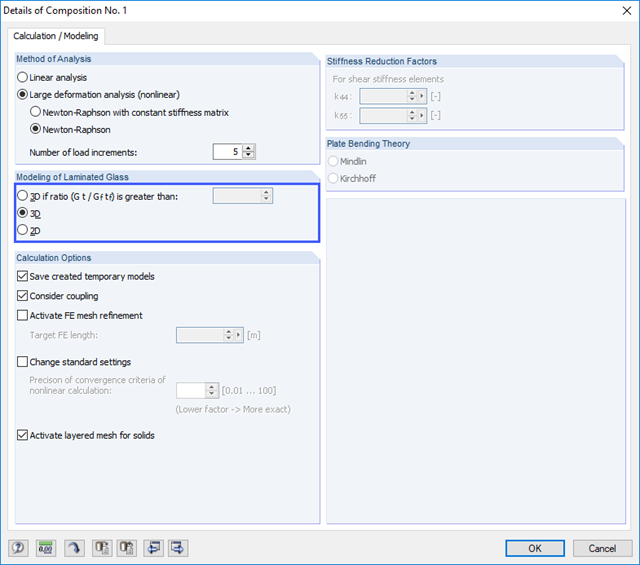
Due to the special properties of glass, you also have to pay close attention to the details when modeling in an FE model. Glass has a very high compressive strength and is, therefore, generally only designed for its tensile stresses. One particular disadvantage of the material is its brittleness. Stress peaks that occur in the calculation must, therefore, not be readily neglected.
The deformations of the FE nodes are always the first result of an FE calculation. It is possible to calculate strains, internal forces, and stresses based on these deformations and the stiffness of the elements.
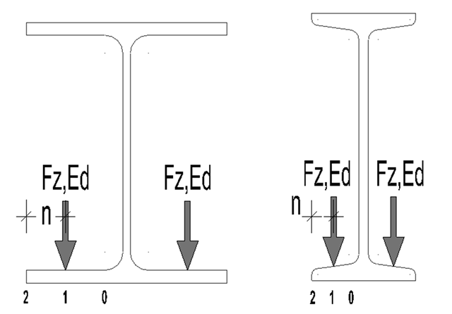
For suspension cranes, the bottom chord of the runway girder is subjected to local flange bending due to the wheel loads in addition to the main load-bearing capacity. The bottom chord behaves like a slab due to these local bending stresses, and has a biaxial stress condition [1].
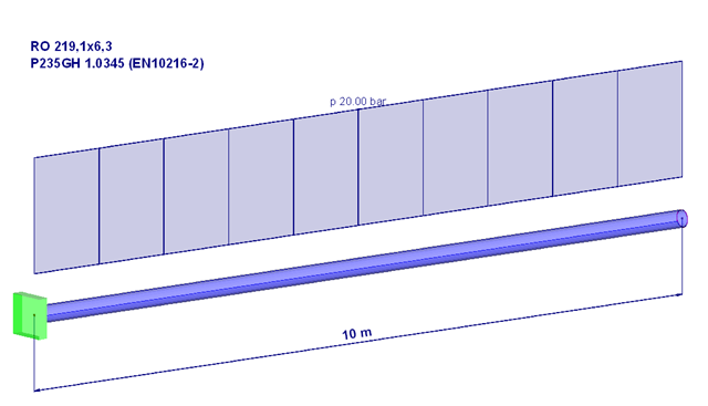
Piping systems are exposed to a variety of loads. One of the most decisive is internal pressure. This article will, therefore, deal with the stresses and deformations resulting from a pure internal compression load in the pipe wall or for the pipe.
![[Edit Parameters] Button in Table Toolbar](/en/webimage/009362/2418341/01-en-png.png?mw=640&hash=c76563b459152b19c98197ea6ba342be89d9a5bc)
The SHAPE‑THIN stand-alone program determines the characteristic values and stresses of any thin‑walled cross‑sections. Graphic tools and features allow for modeling complex cross‑section shapes. In addition to the graphical input, it is also possible to enter the data in tables. As an alternative, you can import a DXF file and use it as a basis for further modelling. Also, each cross-section can be entered using the cross-section library of Dlubal Software and combined as a part with the user-defined elements.
When designing reinforced concrete components according to EN 1992‑1‑1 [1], nonlinear methods of determining internal forces for the ultimate and serviceability limit states are possible. In this case, the internal forces and deformations are determined with respect to their nonlinear behaviour. The analysis of stresses and strains in cracked state usually provides the deflections, which clearly exceed the linearly determined values.
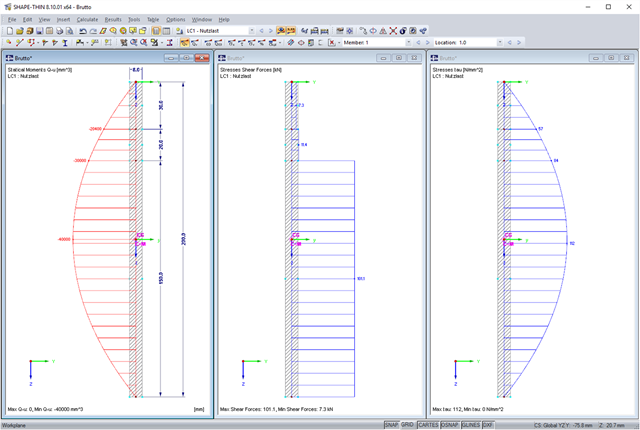
SHAPE-THIN allows you to calculate section properties and stresses of any cross-sections. If a flange or a web is weakened by bolt holes, you can consider this by using null elements. The stresses are subsequently recalculated with the reduced cross-section values. In this case, it is necessary to pay a special attention to shear stresses. By default, these are set to zero in the area of the null elements. When recalculating shear stresses with the reduced cross-section values and without further adaptation, it turns out that the integral of the shear stresses is no longer equal to the applied shear force. The following example shows in detail how to calculate the shear stress.
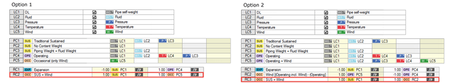
The RF-PIPING and RF-PIPING Design add-on modules allow you to design piping systems according to EN 13480-3 [1], ASME B31.1 and B31.3. In the case of the European standard, the determination of pipe stresses is based on the formulas of Section 12.3 Flexibility Analysis. Depending on the stress type, one or more resulting moments is applied without regard to each other. This differentiation occurs when determining the stresses due to occasional loads, for example.
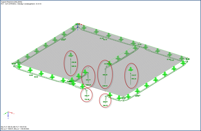
The boundary conditions of a plate support can be entered quickly as singular and line supports in the FEA software. However, if the flexibility of the supports is not considered when modeling the structure, it is often necessary to take a closer look at the support definitions during the design using stresses or the determination of the required reinforcement, at the latest.
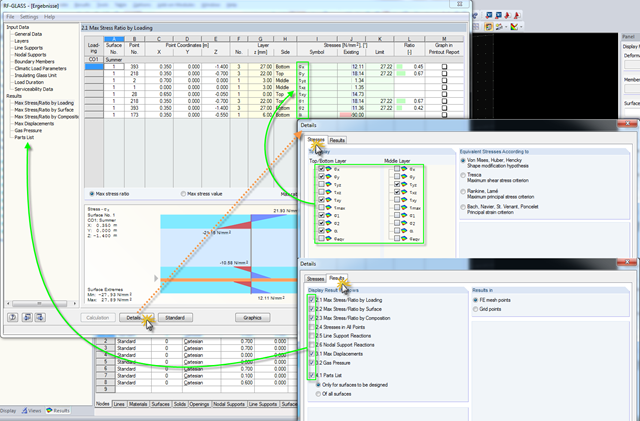
Click the [Details] button in RF-GLASS to select the results to be displayed. In order to get a better overview for the result evaluation, you can select the individual stress graphics (principal stresses, stresses oriented to axes, shear stresses) as well as various result windows. This way, you can show only the results you require.

Silos are used as large containers for storage of bulk materials such as agricultural products or source materials as well as intermediates of industrial production. The structural engineering of such structures requires a precise knowledge of the stresses due to particulate solids in the building structure. The standard EN 1991‑4 "Actions on Silos and Tanks" [1] provides the general principles and requirements for determining these actions.

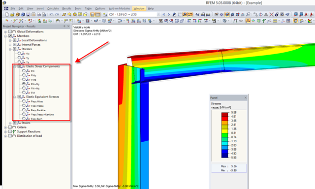
In RF-STEEL Surfaces, it is possible to display the stresses relevant for the design of welds, for example, according to EN 1993‑1‑8, Figure 4.5. When evaluating the stress components, the local xyz-axis system of the surfaces must be considered.
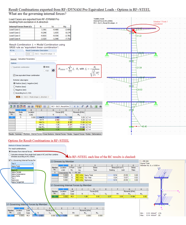
Result combinations exported from RF‑/DYNAM Pro – Equivalent Loads are generated by superimposing the results from the individual modal responses. For this, the SRSS rule can be used as "equivalent linear combination". When result combinations are used in RF‑/STEEL, two options are available for calculating stresses. In the first option, the results from the result combinations are used directly. This is done line by line, for each maximum and minimum controlling internal force. In the second option, stresses are determined from the individual load cases. The quadratic superposition rule is then performed again in RF-/STEEL.
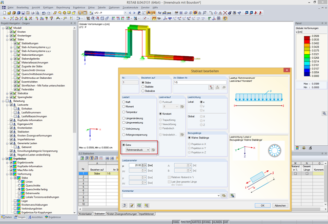
In addition to bending, torsional, longitudinal, and strain loads, you can define and analyze the internal pressure of members with circular hollow cross‑sections in RFEM and RSTAB. The following perimeter and axial stresses resulting from the internal pressure load are analyzed using Barlow's formula and transferred to design modules in order to superimpose the remaining stresses due to internal forces.

In January 2015, DIN Committee NA 005‑08‑23 Steel Bridges applied the introduction of a modification in equation 10.5 of DIN EN 1993‑1‑5. This involves the interaction of longitudinal and transverse pressure in a buckling analysis. Now, the interaction equation provides for auxiliary factor V, which is calculated from the reduction factors of the longitudinal and transverse stresses.
RFEM 5.04.xx allows for graphical visualization of normal and shear stress of members (this feature is available only if the RF‑STEEL add‑on module is licensed).