


Ultimate Limit State
It must be verified that the wheel loads can be absorbed by the bottom chord. In [2], Chapter 6.7, Equation 6.2, the following formula is given:
where
leff = effective length according to [2], Table 6.2
m = lever arm of wheel load at the transition flange-web according to [2], Equation 6.3
σf,Ed = bending stress in the centroidal axis of the flange due to global loading
The following condition must be met:
Fz,Ed ≤ Ff,Rd
The location to design in the runway girder as well as the axle base of the wheel loads have to be considered, particularly for the calculation of the effective length according to [2], Table 6.2.
![Influencing Parameters for Calculating Effective Length According to [2], Tab. 6.2](/en/webimage/009214/2417658/02-en-png.png?mw=760&hash=ca56a0a518bfcbe752b7f572eecf4a08bc73889e)
Serviceability Limit State/Fatigue
For the design of suspension cranes in the serviceability limit state according to [2], it is necessary to determine the local bending stresses in the lower flange due to wheel loads according to [2], Chapter 5.8. The calculation of the necessary coefficients is carried out according to [2], Table 5.2. Furthermore, you have to superimpose the respective global stresses with the local stresses due to the wheel loads in the structural analysis.
According to NCI (Germany) in Chapter 5.8 of EN 1993-6, reducing the local stresses to 75% for this superposition is allowed. This design verifies the elastic behavior of the lower flange.
Local Stresses in the Lower Flange
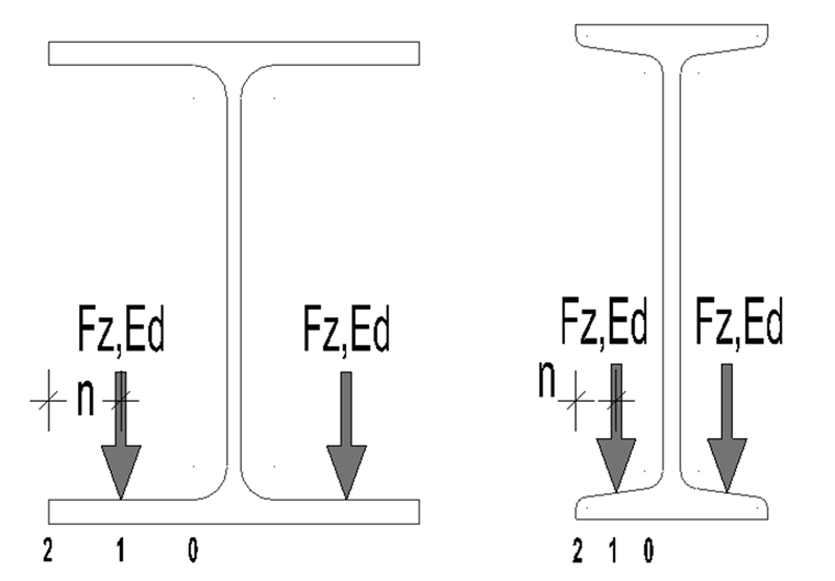
There are different methods to determine the local stresses in the lower flange, which are also shown in [3]. In [2], the calculation according to FEM guideline 9.341 "Local girder stresses" has been taken over. The stresses are calculated here at the local points 0, 1, and 2, as shown in Figure 01.
The stresses are taken from the following formulas:
Longitudinal direction of the beam:
Transversal direction of the beam:
where
cx,i and cy,i according to [2], Table 5.2
It must be noted that the stresses of the individual wheels should be superpositioned in cases of small axle bases xw ≤ 1.5 b (see Figure 02). See [2], Chapter 5.8 (8)
Superposition with Global Stresses
According to [2], Chapter 7.5, the local stresses in the longer flange have to be superimposed with the global stresses from the structural analysis:
where
Summary
Several factors have to be considered for the design of the lower flange. The designed location in the runway girder plays an especially important role for determining the effective length. Furthermore, the axle base of the wheels is important because the wheel loads and their local stresses may be superpositioned in cases of small distances.