144 Wyniki
Wyświetl wyniki:
Sortuj według:
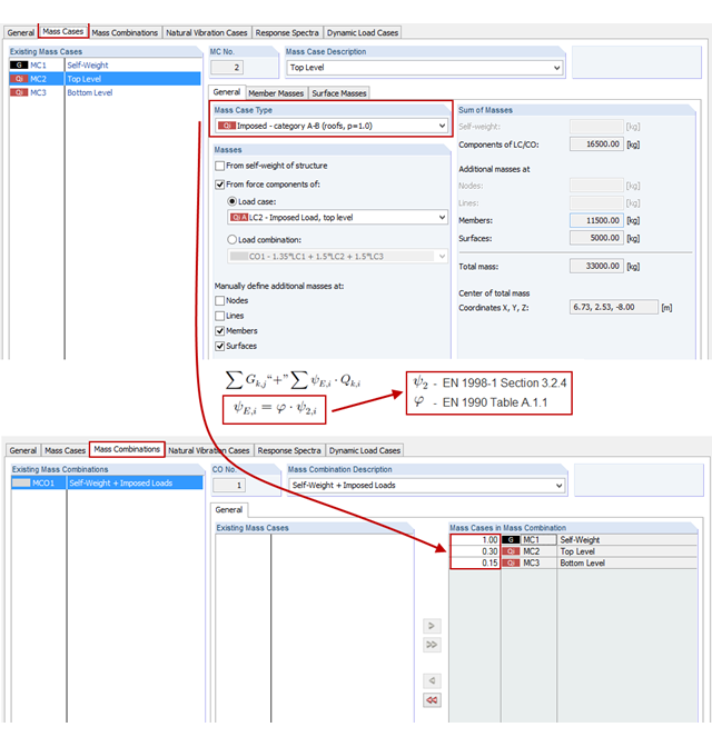
Nowy moduł RF-/DYNAM Pro - Natural Vibrations jest dostępny od wydania programów RFEM w wersji 5.04.xx i RSTAB w wersji 8.04.xx. Massen können nun direkt aus Lastfällen oder Lastkombinationen importiert werden.
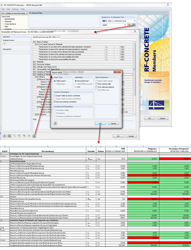
Parametry krajowe EN 1992-1-1 dla każdego kraju można wyeksportować z modułów RF-/CONCRETE, RF-/CONCRETE Columns i RF-/FOUNDATION Pro. Dabei stehen die Schnittstellen zu MS Excel und CSV zur Verfügung. Durch den Export der nationalen Parameter können diese zum Beispiel in MS Excel aufbereitet und eventuelle Unterschiede zwischen einzelnen nationalen Anhängen übersichtlich dargestellt werden (siehe Bild).
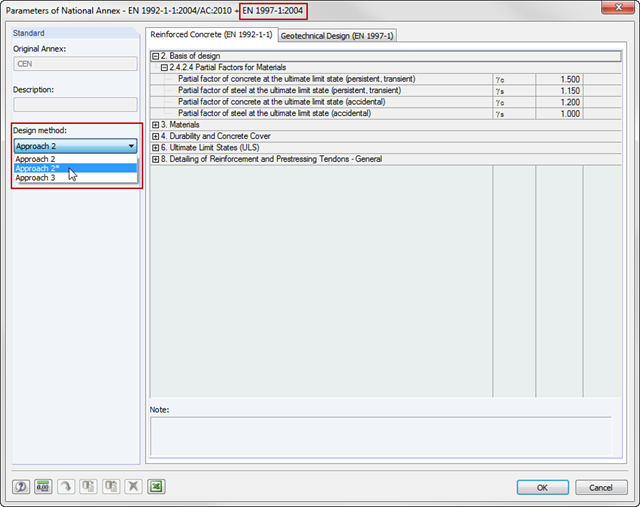
W RF-/FOUNDATION Pro wprowadzono obliczenia geotechniczne pojedynczych fundamentów zgodnie z EN 1997-1 w RFEM 5 i RSTAB 8. Je nachdem, welcher Nationale Anhang im Modul voreingestellt wurde, wurde die Ermittlung des Grundbruchwiderstandes bis zur Version x.04.0108 mit dem Verfahren 2 beziehungsweise 3 gemäß EN 1997-1 ermöglicht.
W wersji x.06.1103 dostępne są różne opcje optymalizacji. Auch im Modul RF-/FUND Pro wurden Weiterentwicklungen realisiert.
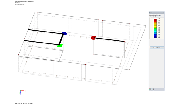
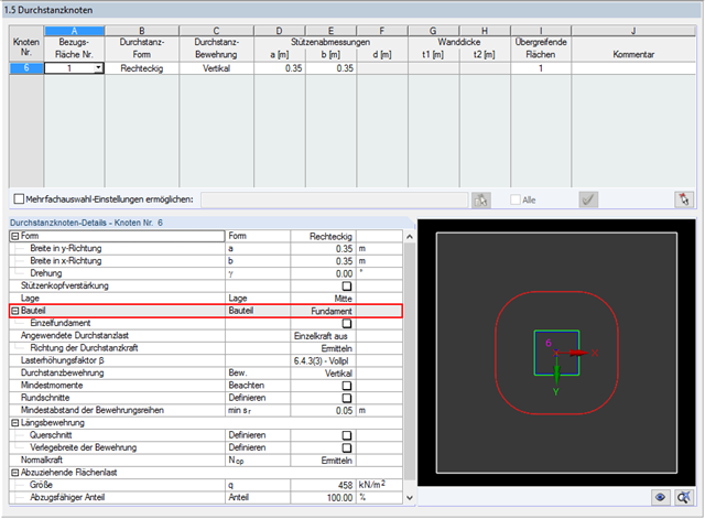
Moduł dodatkowy RF-PUNCH Pro umożliwia przeprowadzanie wymiarowania płyt stropowych i fundamentowych na przebicie przez ścinanie na końcach i narożach ścian.
W przypadku elementów płytowych obliczenie siły tnącej musi być przeprowadzone w miejscach z oddziaływaniem obciążenia skupionego, stosując zasady obliczania wytrzymałości na przebicie zgodnie z rozdz. 6.4 normy EN 1992-1-1 [1]. Eine konzentrierte Lasteinleitung liegt an Einzelstellen zum Beispiel durch eine Stütze, konzentrierte Einzellast oder Punktauflager vor. Zusätzlich ist das Ende einer linienförmigen Lasteinleitung in Flächen auch als konzentrierte Lasteinleitung zu werten. Darunter fallen beispielsweise Wandenden, Wandecken, Enden beziehungsweise Ecken von Linienlasten und Linienlagern. Der Durchstanznachweis ist für Platten und Bodenplatten beziehungsweise Fundamenten unter der Berücksichtigung der um den betrachteten Durchstanzpunkt vorhandenen Plattentopologie zu führen. Im Zuge des Durchstanznachweises nach EN 1992-1-1 ist zu prüfen, dass die einwirkende Querkraft vEd den Widerstand vRd nicht übersteigt.
![Redukcja budynku do konstrukcji wspornikowej. Kondygnacje stanowią poszczególne punkty masy. Ugięcie spowodowane normalnymi siłami ściskającymi pokazanymi w (a) jest (b) przeliczane na równoważne momenty przemieszczenia lub siły tnące [2]]](/pl/webimage/009762/467694/01-de-png.png?mw=640&hash=52805a227240ecddbd69b1d113348bf2749c3f9e)
Zgodnie z EN 1998-1 sekcje 2.2.2 i 4.4.2.2 [1] do sprawdzania stanu granicznego nośności należy przeprowadzić obliczenia z uwzględnieniem teorii drugiego rzędu (efekt P-Δ). Dieser Einfluss darf nur vernachlässigt werden, wenn der Empfindlichkeitsbeiwert der gegenseitigen Stockwerksverschiebung θ kleiner 0,1 ist.
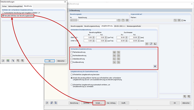
Alternatywą dla tradycyjnego, automatycznego rozmieszczania zbrojenia powierzchniowego w RF-CONCRETE Surfaces, jest również ustawienie go zgodnie z indywidualnymi wymaganiami. Dies ist beispielsweise für die Erstellung von Bewehrungsplänen von Vorteil, da hier die Bewehrungsbereiche klar definiert und auch bemaßt werden können.
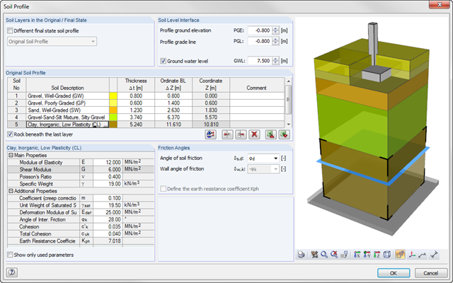
Począwszy od wersji x.06.1103, istnieje możliwość wprowadzenia profilu gruntu w RF-/FOUNDATION Pro. Für den Anwender bietet dies den Vorteil, dass über und unter der Fundamentsohle mehrere Bodenschichten mit verschiedenen Bodenparametern angesetzt werden können. Für die Eingabe der Bodenschichten steht eine Bibliothek mit verschiedenen Böden zur Verfügung, welche auch durch benutzerdefinierte Böden erweitert werden kann. Das vom Anwender definierte Bodenprofil wird in der interaktiven Infografik dargestellt. Jede Änderung, zum Beispiel an den Schichtdicken, wird unmittelbar grafisch dargestellt.
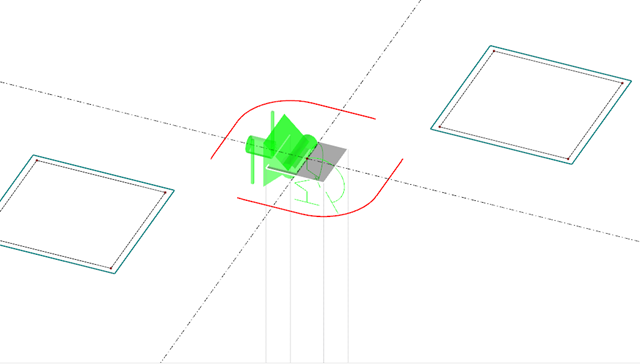
Moduł dodatkowy RF-PUNCH Pro umożliwia przeprowadzenie obliczeń płyt stropowych i fundamentowych na przebicie zgodnie z EN 1992-1-1. Bei einer Deckenplatte wird der kritische Rundschnitt gemäß 6.4.2 (1), EN 1992-1-1 [1] in einem Abstand von 2 d von der Lasteinleitungsfläche angenommen.
W konstrukcjach żelbetowych często stosuje się podciągi lub belki teowe. Im Gegensatz zu früheren Möglichkeiten zur Abbildung und Berechnung dieser Problematik, wo ein Unterzug zum Beispiel als festes Lager angenommen und die ermittelte Lagerreaktion auf ein separates Stabsystem mit Plattenbalkenquerschnitt angesetzt wurde, bieten komplexe FE-Programme wie RFEM die Möglichkeit, das System als Ganzes und somit genauer zu berücksichtigen.
![Składowe rozrachunku zależne od czasu [2]](/pl/webimage/009673/467480/01-de-png.png?mw=640&hash=52805a227240ecddbd69b1d113348bf2749c3f9e)
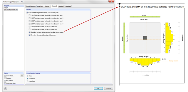
W przypadku obliczeń stanu granicznego użytkowalności zgodnie z sekcją 6.6 Eurokodu EN 1997-1, osiadania należy obliczyć dla fundamentów bezpośrednich. In RF-/FUND Pro wurde die Setzungsberechnung für ein Einzelfundament ermöglicht. Dabei kann zwischen der Setzungsberechnung für ein schlaffes oder starres Fundament gewählt werden. Durch die Definition eines Bodenprofils ist die Berücksichtigung mehrerer Bodenschichten unter der Fundamentsohle möglich. Die Ergebnisse der Setzung, Fundamentverkantung und der vertikalen Sohlspannungsverteilung sind sowohl grafisch als auch tabellarisch aufbereitet und verschaffen so einen schnellen Überblick über die durchgeführte Berechnung. Zusätzlich zum Nachweis der Fundamentsetzung in RF-/FUND Pro werden die repräsentativen Federkonstanten für das Auflager in der statischen Berechnung bestimmt und können auf Wunsch in das statische Modell von RFEM oder RSTAB exportiert werden.
![Eigenspannungen, Nulllinienlage und Einrisstiefe bei beidseitiger Abkühlung einer Scheibe [2]](/pl/webimage/009621/2419691/01-en-png-1-png.png?mw=640&hash=6901ae948a4557b4cac04831fbbb5082a4d4aaf3)
Zasadniczo unikanie spękań w konstrukcjach betonowych nie jest ani możliwe, ani konieczne. Jednak zarysowania należy ograniczyć w taki sposób, aby nie zakłócić prawidłowego użytkowania, wyglądu i trwałości konstrukcji. Dlatego ograniczenie szerokości spękań nie oznacza zapobiegania powstawaniu spękań, ale ograniczenie szerokości spękań do nieszkodliwych wartości.
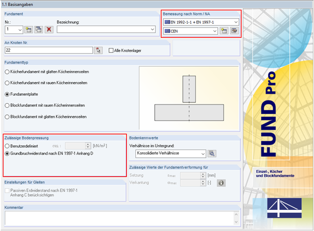
Oprócz wymiarowania betonu zbrojonego zgodnie z EN 1992-1-1, RF-/FOUNDATION Pro umożliwia przeprowadzanie obliczeń geotechnicznych zgodnie z EN 1997-1. W RF-/FOUNDATION Pro, wymiarowanie dopuszczalnego parcia gruntu jest przeprowadzane jako wymiarowanie odporności na zniszczenie gruntu. Wird als Nationaler Anhang CEN ausgewählt, stehen dem Anwender zwei Möglichkeiten für die Definition des Grundbruchwiderstandes zur Verfügung. Zum einen kann der zulässige charakteristische Wert der Sohlspannung σRk vom Benutzer direkt vorgegeben werden. Zum anderen besteht auch die Möglichkeit der analytischen Ermittlung der zulässigen Bodenpressung nach [1] Anhang D.
![Parameter der mitwirkenden Plattenbreite (Bild 5.3 [1])](/pl/webimage/009561/467194/01-de.png?mw=640&hash=9f6ca6566391e0348354d64018782d9ffd5f7c70)
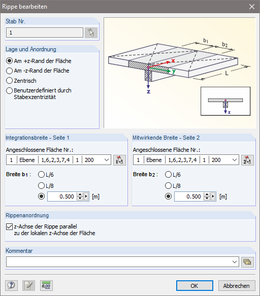
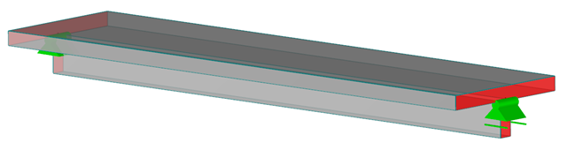
W przypadku kombinacji konstrukcji MES (elementy powierzchniowe i prętowe) lub konstrukcji płytowych, do obliczeń konstrukcji prętowej można przypisać fikcyjny przekrój belki teowej, którego geometria zależy od efektywnego szerokość. In RFEM wird bei Verwendung des Stabtyps "Rippe" die Steifigkeit durch einen Plattenanteil (Flächenelement) und einen Steganteil (Stabelement) abgebildet. Diese Vorgehensweise bringt für die Bemessung Besonderheiten mit sich, auf die im Folgenden eingegangen werden soll.
![Układ konstrukcyjny dla Schöck Isokorb® Typ K z [1]](/pl/webimage/009555/467176/01-de.png?mw=640&hash=9f6ca6566391e0348354d64018782d9ffd5f7c70)
Straty ciepła spowodowane przez elementy zewnętrzne bez rozłączenia termicznego elementów wewnętrznych są ogromne. Z tego powodu zewnętrzne elementy konstrukcyjne są oddzielone termicznie od przegród zewnętrznych budynku za pomocą specjalnego elementu. Do połączenia płyty balkonowej ze stropem żelbetowym można wykorzystać np. połączenie Schöck Isokorb® lub HALFEN HIT. Przy wymiarowaniu takich elementów wbudowanych należy uwzględnić odpowiednią aprobatę techniczną. Poniższy artykuł pokazuje przykład uwzględnienia Schöck Isokorb® w obliczeniach MES.
![Model obliczeniowy dla nośności połączenia klejonego według [1]](/pl/webimage/009526/467105/01-de.png?mw=640&hash=9f6ca6566391e0348354d64018782d9ffd5f7c70)
W procesie budowlanym często konieczne jest tworzenie elementów betonowych w przekrojach. Ein klassisches Beispiel für diese abschnittsweise Herstellung ist die Verwendung von Fertigteilunterzügen, bei denen die Platte in Ortbetonbauweise ergänzt wird. Die Ergänzung eines Querschnittsteils führt zu einer Entstehung von Fugen zwischen bereits erhärtetem Beton und Frischbeton. Die Übertragung der zwischen den Teilquerschnitten entstehenden Längsschubkräfte muss bei der Bemessung berücksichtigt werden.
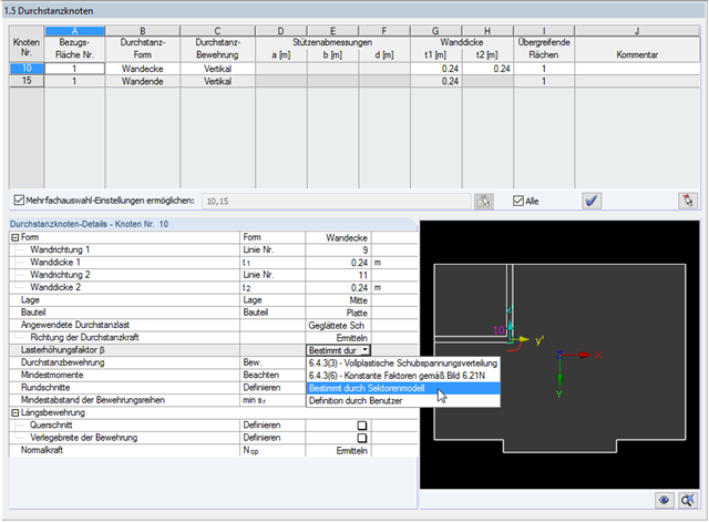
Moduł dodatkowy RF-PUNCH Pro umożliwia przeprowadzanie obliczeń przebicia zgodnie z EN 1992-1-1 [1]. Neben den Nachweisen an Einzelstützen können in RF-STANZ Pro auch Wandenden und Wandecken analysiert werden.An dieser Stelle ist auch auf einen früheren Fachbeitrag zu RF-STANZ Pro hinzuweisen, in welchem die Ermittlung der Durchstanzlast an Wandenden und Wandecken beschrieben wird.
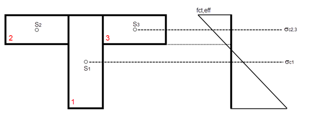
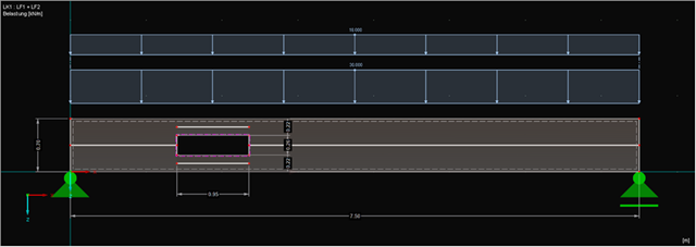
Zgodnie z punktem 7.3.2 (2) norma DIN EN 1992-1-1 wymaga: "Bei gegliederten Querschnitten wie Hohlkästen oder Plattenbalken ist in der Regel die Mindestbewehrung für jeden Teilquerschnitt (Gurte und Stege) einzeln nachzuweisen."Bei einem Plattenbalken mit T-Querschnitt sollte eine Ermittlung der Mindestbewehrung für die beiden Gurte und den Steg durchgeführt werden, wenn die entsprechenden Teilquerschnitte im Zugbereich liegen. Die Einteilung der Querschnitte ist in Bild 01 dargestellt.
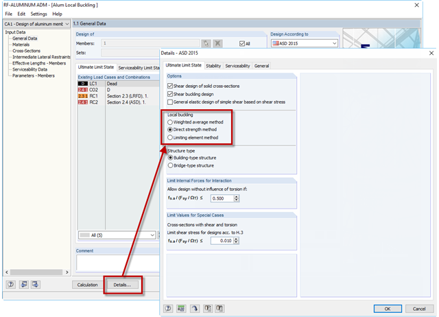
Jeżeli przekrój pręta aluminiowego składa się z smukłych elementów, uszkodzenie może wystąpić z powodu lokalnego wyboczenia pasów lub środników, zanim pręt osiągnie pełną wytrzymałość. W module dodatkowym RF-/ALUMINIUM ADM dostępne są teraz trzy opcje określania nominalnej wytrzymałości na zginanie dla stanu granicznego wyboczenia lokalnego, Mnlb, z rozdziału F.3 w Podręczniku projektowania konstrukcji aluminiowych 2015. Trzy opcje obejmują sekcje F.3.1 Metoda średniej ważonej, F.3.2 Metoda wytrzymałości bezpośredniej i F.3.3 Metoda elementów ograniczających.
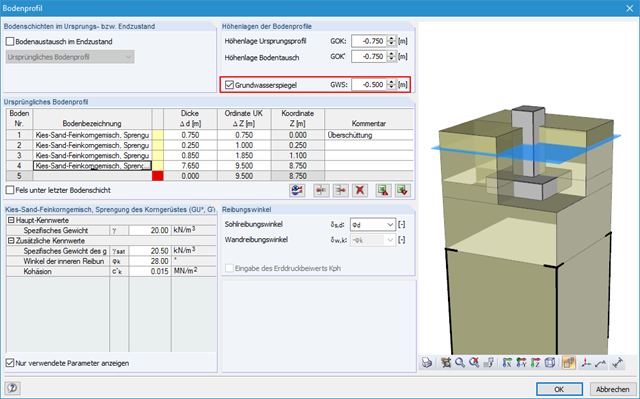
Za pomocą modułu RF-/FOUNDATION Pro można przeprowadzać obliczenia geotechniczne zgodnie z EN 1997-1 [1] dla fundamentów pojedynczych. Następnie program wyświetla szczegółowe informacje na temat wpływu poziomu wody gruntowej na wybrane obliczenia zgodnie z EN 1997-1.
Program RFEM i moduły dodatkowe RF-CONCRETE umożliwiają analizę odkształceń belki teowej w stanie zarysowanym (stan II). Niniejszy artykuł opisuje metody obliczeń (O) i opcje modelowania (M). Zarówno metody obliczeń, jak i opcje modelowania nie ograniczają się do belek teowych, ale zostaną wyjaśnione jedynie na przykładzie tego układu.
![Linia pokrycia rozciąganego od [1]](/pl/webimage/009390/466758/01-de.png?mw=640&hash=9f6ca6566391e0348354d64018782d9ffd5f7c70)
W przypadku dużej ilości zbrojenia, korzystne może być stopniowanie zbrojenia podłużnego belki, co oznacza: ograniczenie. Klasyfikacja odpowiada rozkładowi sił rozciągających. Za pomocą modułów RF-CONCRETE Members i CONCRETE można określić zmniejszenie zbrojenia, które zostanie uwzględnione w automatycznie proponowanym zbrojeniu dla zbrojenia podłużnego. Przy określaniu tej propozycji zbrojenia należy upewnić się, że może zostać przeniesiony obwiednia działającej siły rozciągającej.
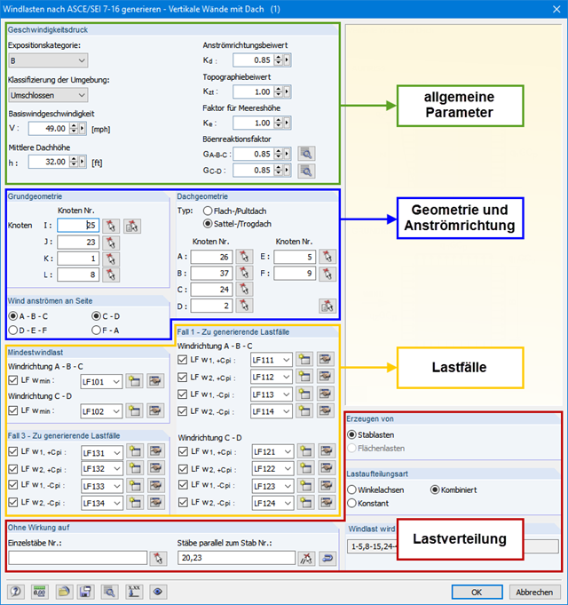
Programy RFEM i RSTAB umożliwiają łatwe uwzględnienie wpływu obciążenia wiatrem na budynek trójwymiarowy zgodnie z ASCE/SEI 7-16. W tym artykule wyjaśniono złożoną teorię wprowadzania obciążeń wiatrem do programu. Obciążenie wiatrem można znaleźć w "Narzędzia" → "Generować obciążenia" → "Od obciążeń wiatrem".
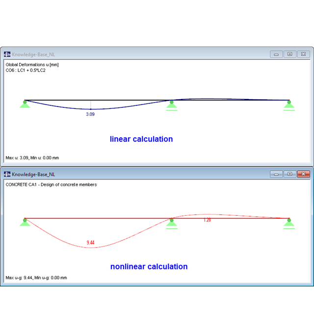
Podczas wymiarowania elementów z betonu zbrojonego zgodnie z EN 1992-1-1 [1] możliwe są nieliniowe metody wyznaczania sił wewnętrznych dla stanów granicznych nośności i użytkowalności. W tym przypadku siły wewnętrzne i odkształcenia są określane z uwzględnieniem ich nieliniowego zachowania. Analiza naprężeń i odkształceń w stanie zarysowanym zazwyczaj wskazuje, że ugięcia wyraźnie przekraczają wartości określone liniowo.
![Formelzeichen beim Anschluss zwischen Gurten und Steg (Quelle: [1])](/pl/webimage/009346/466646/01-de.png?mw=640&hash=9f6ca6566391e0348354d64018782d9ffd5f7c70)
Aby zapewnić oddziaływanie paneli, które powinny działać jak pasy rozciągane lub ściskane, konieczne jest połączenie ich ze środnikiem w sposób odporny na ścinanie. Połączenie to uzyskuje się w podobny sposób, jak w przypadku przenoszenia ścinania w połączeniu między sekcjami betonowanymi, poprzez wykorzystanie interakcji między krzyżulcami ściskanymi a ściągami. Aby zapewnić nośność na ścinanie, należy sprawdzić, czy nośność krzyżulca ściskanego jest podana, a siła ściągająca może zostać przeniesiona przez zbrojenie poprzeczne.
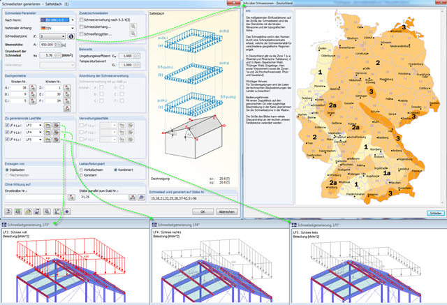
Eurokod 1, części 1 do 3 oraz norma amerykańska ASCE/SEI 7-16 opisują efekty ogólne od obciążeń śniegiem. Die von den Normen geforderten Lastansätze für Sattel-, Pult- und Flachdächer sind in RFEM und RSTAB in einem Tool hinterlegt, sodass eine einfache Generierung dieser Einwirkung stattfinden kann.
Za pomocą modułu RF-/FOUNDATION Pro można przeprowadzać obliczenia geotechniczne zgodnie z EN 1997-1 [1] dla fundamentów pojedynczych. Im nachfolgenden Beitrag wird auf den Nachweis der Fundamentverdrehung nach DIN EN 1997-1, A 6.6.5 (siehe [3]) eingegangen.
![Spektrale Beschleunigung Sa [m/s²] versus Eigenfrequenz f [Hz] eines schmalbandigen Antwortspektrums nach EN 1998-1 [1]](/pl/webimage/009251/466397/01-de.png?mw=640&hash=9f6ca6566391e0348354d64018782d9ffd5f7c70)
In einem multimodalen Antwortspektrenverfahren ist es wichtig, eine ausreichende Anzahl von Eigenwerten der Struktur zu ermitteln und deren dynamische Antworten zu berücksichtigen. Vorschriften wie die EN 1998-1 [1] und andere internationale Standards schreiben vor, 90 % der Strukturmasse zu aktivieren. To oznacza: so viele Eigenwerte zu bestimmen, dass die Summe der effektiven Modalmassenfaktoren größer 0.9 ist.
Ponieważ w rejonie otworów stan graniczny nośności belek jest zaburzony, należy zwrócić na to szczególną uwagę. Ogólnie, niewielkie otwory można wkomponować w konstrukcję belki i pominąć w obliczeniach. W przypadku dużych otworów, konieczne jest uwzględnienie i zamodelowanie takiego rejonu osobno.