43 Wyniki
Wyświetl wyniki:
Sortuj według:

W artykule przedstawiono równania wykorzystywane przez program do określenia podpór podporowych na podstawie parametrów słupa.

Aby ocenić, czy w obliczeniach dynamicznych konieczne jest również uwzględnienie analizy drugiego rzędu, w normie EN 1998‑1, sekcje 2.2.2 i 4.4.2.2 zawarto współczynnik wrażliwości międzykondygnacyjnego znoszenia θ. Można ją obliczyć i przeanalizować za pomocą programów RFEM 6 i RSTAB 9.
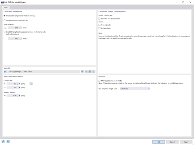
W tym artykule pokazano, jak tworzyć przekroje przy użyciu plików DXF.
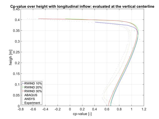
W tym artykule porównujemy wyniki z programów RWIND, ABAQUS i ANSYS z badaniem w tunelu aerodynamicznym przy użyciu prostego geometrycznie modelu.
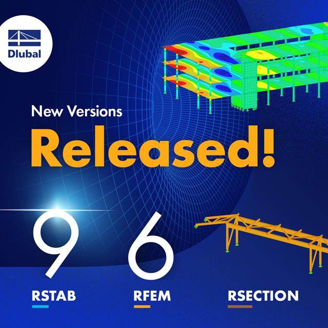
Wraz z programami do analizy statyczno-wytrzymałościowej RFEM 6, RSTAB 9, RSECTION 1 i RWIND 2, Dlubal Software przedstawia nową generację programów do analizy statyczno-wytrzymałościowej. Getreu dem Motto „Statik, die Spaß macht…“ werden den Anwendern universelle Werkzeuge in die Hand gegeben, mit denen alle Anforderungen in der Tragwerksplanung bewältigt werden können. Was sich sonst noch bei Dlubal Software Neues getan hat, erfahren Sie in diesem Artikel.
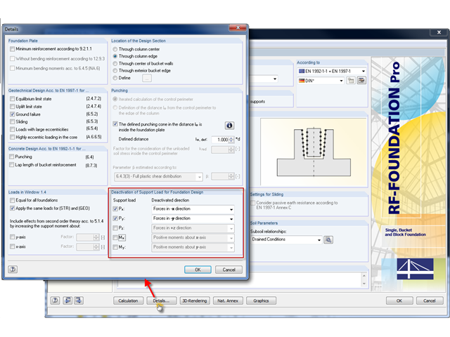
Bei der Modellierung von statischen Tragsystemen, insbesondere von Hallentragwerken, kann es vorkommen, dass einige Konstruktionen im Gründungsbereich, welche für das aufgehende Tragwerk ohne Einfluss sind, in RFEM beziehungsweise RSTAB nicht modelliert werden. Dabei handelt es sich bei Hallentragwerken beispielsweise um Stahlbeton-Bodenplatten, Streifenfundamente oder Zugbänder zwischen den Stützenfundamenten.
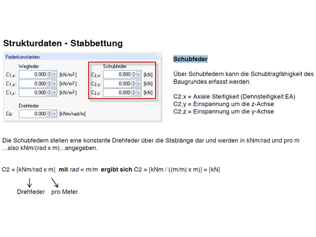
Do pręta można przypisać podłoże sprężyste. Damit wird in der Regel der Einfluss des Baugrundes in die Modellierung einbezogen. Bettungen können nur für den Stabtyp "Balkenstab" definiert werden.
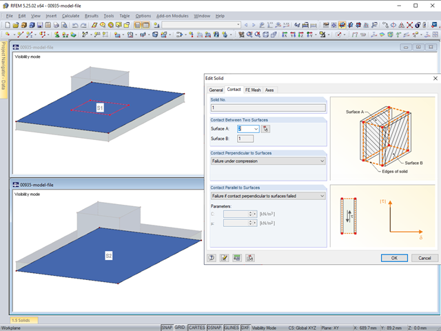
Die Kontakteigenschaften zwischen zwei Flächen können in RFEM mit Hilfe von Kontaktvolumen abgebildet werden. Bei der Modellierung ist unter anderem zu beachten, dass in der Regel beide Kontaktflächen eines Kontaktvolumens die gleichen integrierten Objekte aufweisen sollten. Es empfiehlt sich daher, gleich bei der Anlage der Kontaktflächen die zweite Kontaktfläche durch Kopieren zu erstellen.
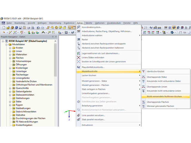
Bei der Modellierung eines Systems oder nach einem Import kann es vorkommen, dass Linien der Länge Null entstehen.
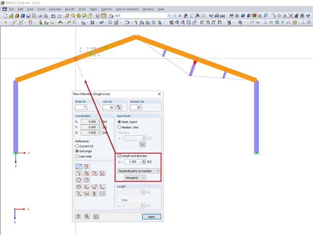
W przypadku wzmocnienia cięgnami pręty ściskane należy modelować prostopadle do nachylonej belki głównej. W tym przypadku znana jest długość pręta oraz punkt przecięcia z belką.
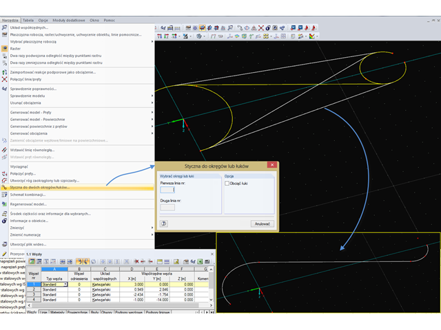
In RFEM stehen verschiedene Tools für die Modellierung zur Verfügung. Diese Funktionen ermöglichen ein schnelles und effektives Abbilden von komplizierten Strukturen im Programm. Die Verbindung zweier Kreise oder Bögen beispielsweise kann mit der Funktion "Tangente zu Kreisen oder Bögen" hergestellt werden.
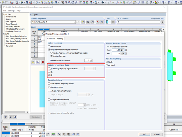
Bei der Glasbemessung im Zusatzmodul RF-GLAS stehen grundsätzlich zwei verschiedene Berechnungsoptionen zur Verfügung: eine 2D- und eine 3D-Berechnung. Grundsätzlicher Unterschied dieser beiden Bemessungsvarianten ist die vom Programm automatisierte Modellierung der Scheiben im temporären Modell. Bei einer 2D-Bemessung werden für die einzelnen Scheiben gängige Flächenelemente (Plattentheorie) generiert, während bei der 3D-Bemessung die einzelnen Scheiben als Volumen abgebildet werden. Je nach gewähltem Schichtaufbau steht die Option zur Wahl oder wird vom Programm bereits automatisch vorgegeben.
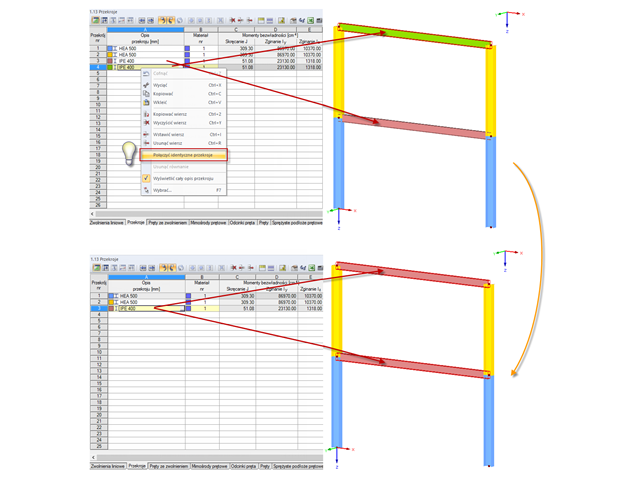
Bei der Modellierung von komplexeren Tragwerken mit einem erhöhten Wiederholungsgrad treten identische Material- und Querschnittsdefinitionen häufig auf.
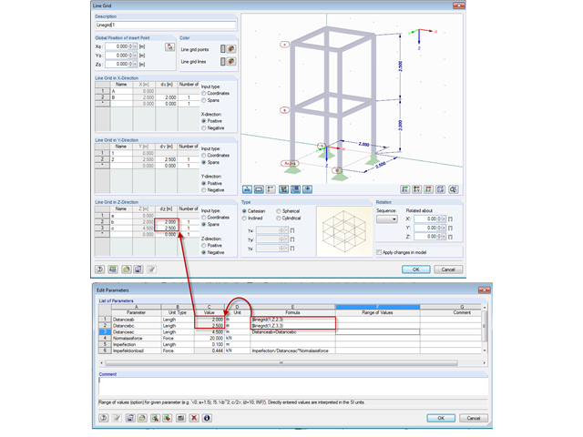
In der Formeleditor-Umgebung können beliebige Parameter (Längen, Kraftgrößen etc.) zur Steuerung von Last- und Geometrieangaben in der Modellierung angegeben werden.
Bei einem wandartigen Tragverhalten der Brettsperrholzplatte muss der Schubverformung in Scheibenebene und damit insbesondere der Verschieblichkeit der Verbindungsmittel besondere Beachtung geschenkt werden.
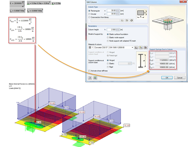
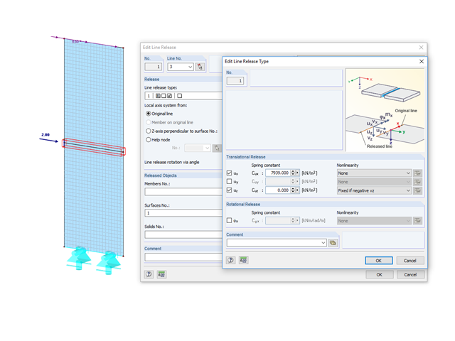
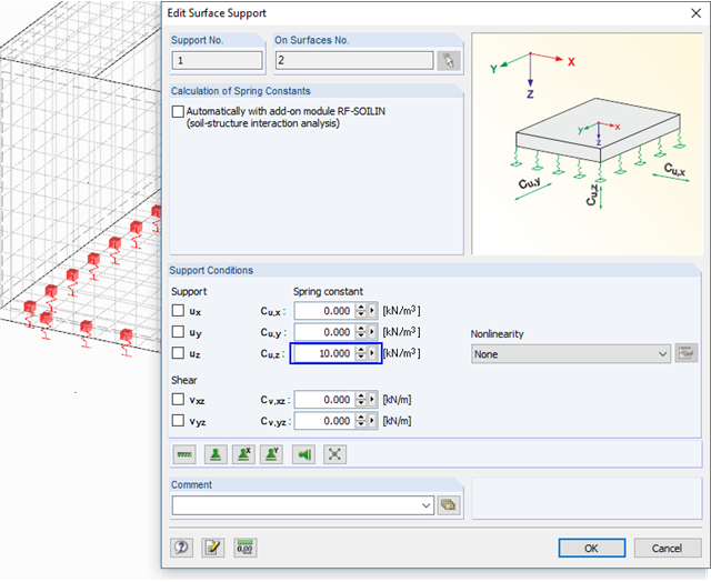
Damit Singularitäten infolge eines festen Knotenlagers in RFEM vermieden werden können, gibt es die die Möglichkeit einer elastischen Lagerung. Diese kann direkt im Dialog des Knotenlagers als Stütze in Z definiert werden. Dabei müssen die Geometrie der Stütze sowie das Material und die Lagerungsbedingungen erfasst werden. In diesem Beitrag soll die Variante der Modellierung der Stütze als Flächenbettung gezeigt werden.
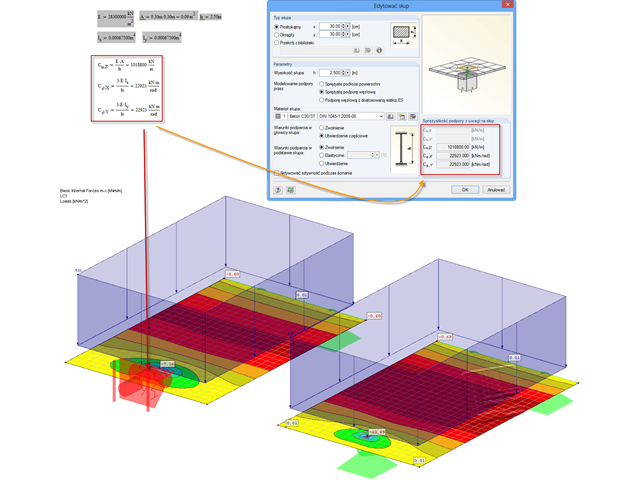
Często w czasie projektowania spotykamy się z tak zwanymi koncentracjami naprężeń w płytach nad podporami. Diese Singularitäten kann man umgehen, indem man das Knotenlager als Stütze modelliert.
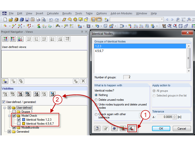
Mit der Modellkontrolle kann gezielt nach Unstimmigkeiten gesucht werden, die sich bei der Modellierung ergeben.
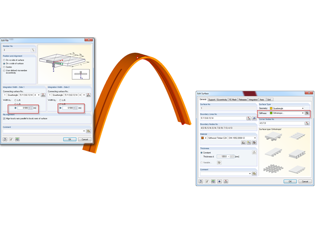
In diesem Beitrag wird die Modellierung von Unterzügen mittels Rippen gezeigt.
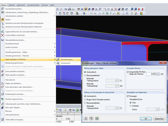
Program RFEM umożliwia automatyczne generowanie powierzchni z modelowanych prętów. Dies bietet den Vorteil, dass beispielsweise die Flächendicken eines Stahlprofils automatisch erzeugt werden.
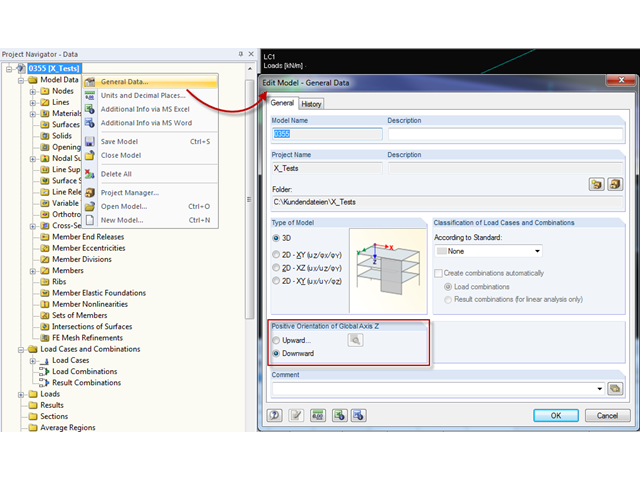
Vor Erstellung eines statischen Modells macht sich jeder Anwender Gedanken über die Randparameter des Systems und wie das Modell am besten abgebildet werden kann. Ein besonderes Augenmerk sollte hierbei auch auf die Orientierung des globalen Koordinatensystems gelegt werden. Im ingenieurtechnischen Bereich wird die globale Z-Achse in der Regel nach unten orientiert (in Richtung der Eigengewichtskraft), wobei sie im architektonischen Bereich meist nach oben ausgerichtet verläuft. Diese Unterschiede können oftmals zu Schwierigkeiten bei der Modellierung führen, beispielsweise beim Austausch von Gesamtmodellen oder DXF-Folien.
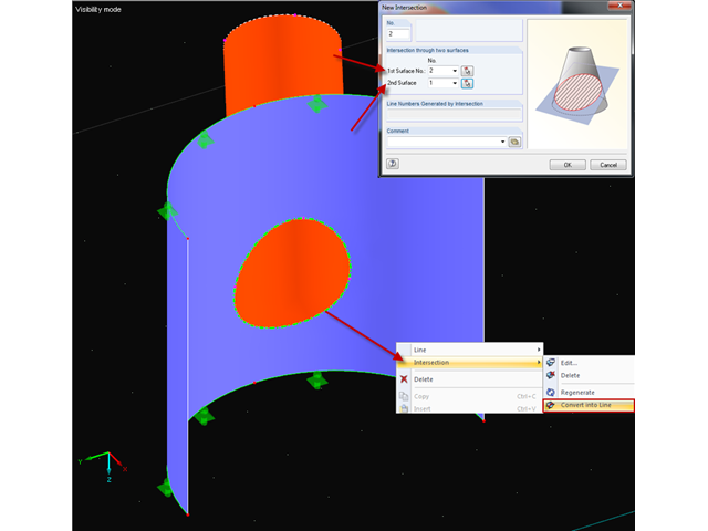
Bei einer Modellierung zweier sich kreuzender Flächen besteht in RFEM die Möglichkeit, die Schnittlinie automatisch erzeugen zu lassen. Programmintern wird diese Funktion als Durchdringung bezeichnet. Bei der Erzeugung einer Durchdringung, wird die modellierte Fläche in Komponenten zerlegt. Dies bietet den Vorteil, dass diese Komponenten bei der Schnittkraftermittlung berücksichtigt oder aber wahlweise auch deaktiviert werden können.
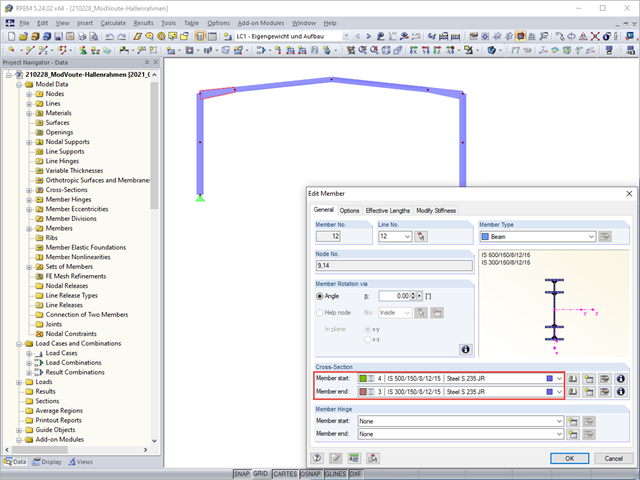
Vouten werden häufig mit coupierten Profilen ausgeführt. Bei der Modellierung sind jedoch einige Besonderheiten zu beachten, damit die Querschnitts- und Stabilitätsnachweise durchgeführt werden können.
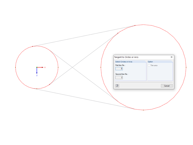
Eine Erleichterung bei der Modellierung stellt die Funktion "Tangente zu Kreisen/Bögen" dar. Dieses Werkzeug befindet sich im Menü "Extras".
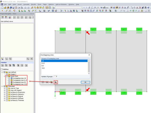
Mitunter können bei der Modellierung in RFEM doppelte Linien entstehen. Damit diese schneller gefunden und gegebenenfalls gelöscht werden können, ist es in RFEM 5 möglich, überlappende Linien zu exportieren. Dies ist beispielsweise nach Excel oder in eine eigene Gruppe der Ausschnitte möglich.
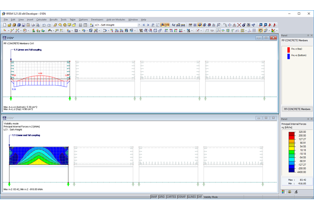
Bei der Abbildung einer Rippe aus Stahlbeton mit darüberstehender Mauerwerkswand besteht die Gefahr einer Unterbemessung der Rippe, wenn das Tragverhalten des Mauerwerks nicht korrekt berücksichtigt und die Verbindung zwischen Mauerwerkswand und Unterzug nicht ausreichend genau modelliert wird. Dieser Artikel soll sich mit dieser Problematik und den möglichen Modellierungen einer solchen Konstruktion auseinandersetzen. Im Beispiel wird die Bewehrung rein aus den Schnittgrößen und ohne jegliche konstruktive Mindestbewehrung ermittelt.
Bei der Modellierung mit finiten Elementen stößt man früher oder später auf die Frage, wie zwei aufeinanderliegende Flächen (2D-Elemente) modelliert werden können. Nicht selten wird der Gedanke umgesetzt, beide Flächen in der gleichen Ebene zu modellieren. Welche Folgen dies haben kann und ob es eventuell bessere Lösungsansätze gibt, soll im Folgenden betrachtet werden.
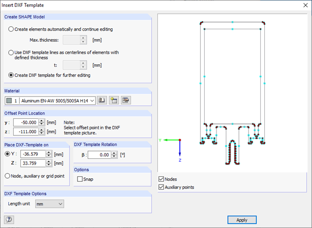
In DUENQ können Querschnittsgeometrien, die als Umriss- oder Schwerelinienmodell im DXF-Format vorliegen, importiert und als Basis für die Modellierung genutzt werden.
.png?mw=640&hash=1be9a846b1f57190540c7fc7f46f44cd40ab7029)
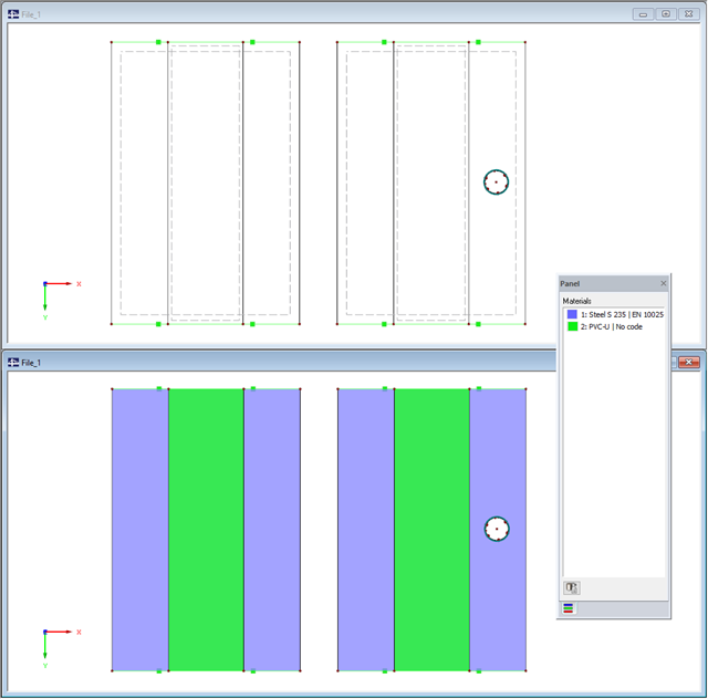
Die Modellierung von flächigen Bauteilen wie Scheiben ist generell nur in RFEM möglich. Jeżeli konieczne jest zdefiniowanie efektu usztywnienia panelu w konkretnym przypadku, można przeprowadzić symulację również w programie RSTAB.
Für die korrekte Modellierung und Berechnung von Schwimmkörpern (spezielle Flöße, Pontons, schwimmende Schiffsanleger, Schwimmbagger, Schwimmhäuser, Schwimminseln, Schwimmkrane, Wohnboote et cetera) ist eine zweistufige Berechnung notwendig.