152 Wyniki
Wyświetl wyniki:
Sortuj według:
![Składowe rozrachunku zależne od czasu [2]](/pl/webimage/009673/467480/01-de-png.png?mw=640&hash=52805a227240ecddbd69b1d113348bf2749c3f9e)
W przypadku obliczeń stanu granicznego użytkowalności zgodnie z sekcją 6.6 Eurokodu EN 1997-1, osiadania należy obliczyć dla fundamentów bezpośrednich. In RF-/FUND Pro wurde die Setzungsberechnung für ein Einzelfundament ermöglicht. Dabei kann zwischen der Setzungsberechnung für ein schlaffes oder starres Fundament gewählt werden. Durch die Definition eines Bodenprofils ist die Berücksichtigung mehrerer Bodenschichten unter der Fundamentsohle möglich. Die Ergebnisse der Setzung, Fundamentverkantung und der vertikalen Sohlspannungsverteilung sind sowohl grafisch als auch tabellarisch aufbereitet und verschaffen so einen schnellen Überblick über die durchgeführte Berechnung. Zusätzlich zum Nachweis der Fundamentsetzung in RF-/FUND Pro werden die repräsentativen Federkonstanten für das Auflager in der statischen Berechnung bestimmt und können auf Wunsch in das statische Modell von RFEM oder RSTAB exportiert werden.
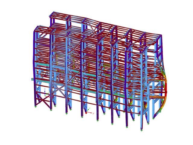
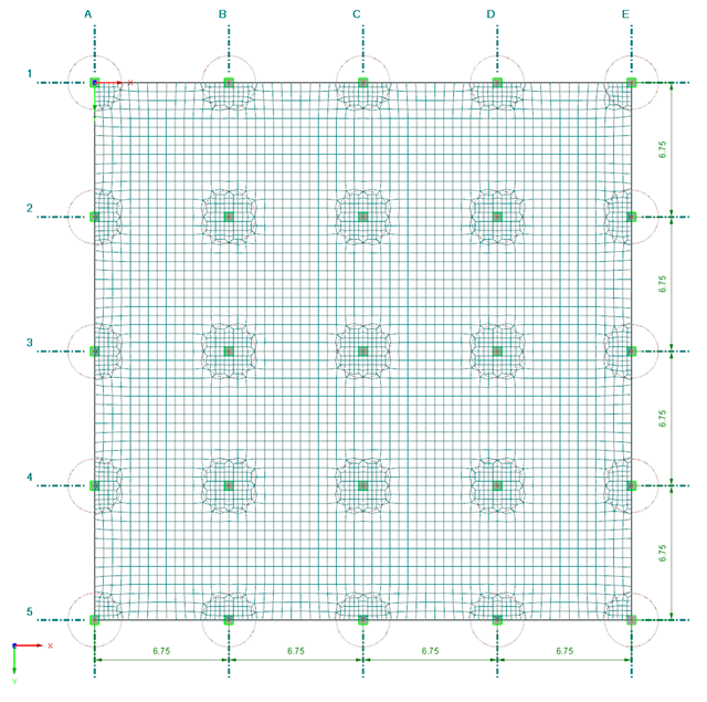
Konstrukcje budowlane są z natury trójwymiarowe. W przeszłości przeprowadzanie obliczeń na układach trójwymiarowych z punktu widzenia praktycznego było bardzo trudne. Dlatego konstrukcje upraszczano i dzielono na płaskie podukłady. Wraz ze wzrostem wydajności komputerów oraz związanego z nimi oprogramowania, coraz częściej możemy zrezygnować z tych uproszczeń. Trend ten wzmacniają nowe technologie cyfrowe, takie jak Building Information Modelling (BIM) czy też nowe możliwości tworzenia realistycznych wizualizacji trójwymiarowych. Czy jednak rzeczywiście model 3D mają przewagę nad podejściem tradycyjnym czy to tylko kwestia aktualnej mody? Poniżej przedstawiono niektóre argumenty przemawiające za stosowaniem modeli 3D konstrukcji.
![Spektrale Beschleunigung Sa [m/s²] versus Eigenfrequenz f [Hz] eines schmalbandigen Antwortspektrums nach EN 1998-1 [1]](/pl/webimage/009251/466397/01-de.png?mw=640&hash=9f6ca6566391e0348354d64018782d9ffd5f7c70)
In einem multimodalen Antwortspektrenverfahren ist es wichtig, eine ausreichende Anzahl von Eigenwerten der Struktur zu ermitteln und deren dynamische Antworten zu berücksichtigen. Vorschriften wie die EN 1998-1 [1] und andere internationale Standards schreiben vor, 90 % der Strukturmasse zu aktivieren. To oznacza: so viele Eigenwerte zu bestimmen, dass die Summe der effektiven Modalmassenfaktoren größer 0.9 ist.
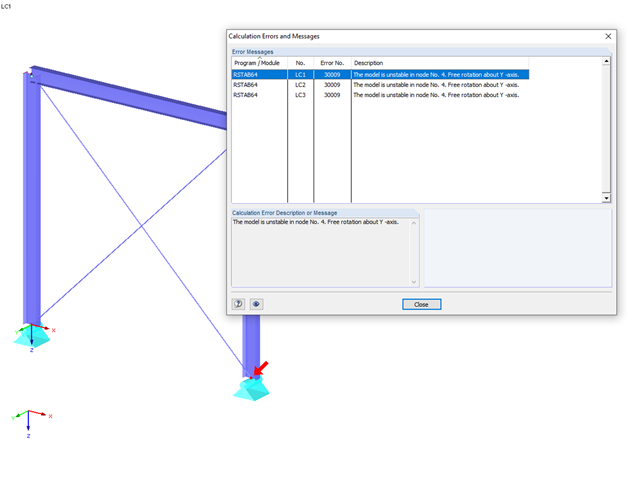
Die häufigste Ursache für instabile Modelle sind ausfallende Stabnichtlinearitäten wie Zugstäbe. Als einfachstes Beispiel dient dazu ein Rahmen, dessen Stützen am Fußpunkt gelenkig gelagert sind und am Stützenkopf Momentengelenke aufweisen. Dieses labile System soll durch einen Kreuzverband aus Zugstäben stabilisiert werden. Bei Lastkombinationen mit horizontalen Lasten bleibt dieses System stabil. Wird es jedoch ausschließlich vertikal belastet, fallen beide Zugstäbe aus und das System wird instabil, was zu einem Berechnungsabbruch führt. Dies lässt sich vermeiden, indem die besondere Behandlung der ausfallenden Stäbe unter "Berechnung" → "Berechnungsparameter" → "Globale Berechnungsparameter" aktiviert wird.
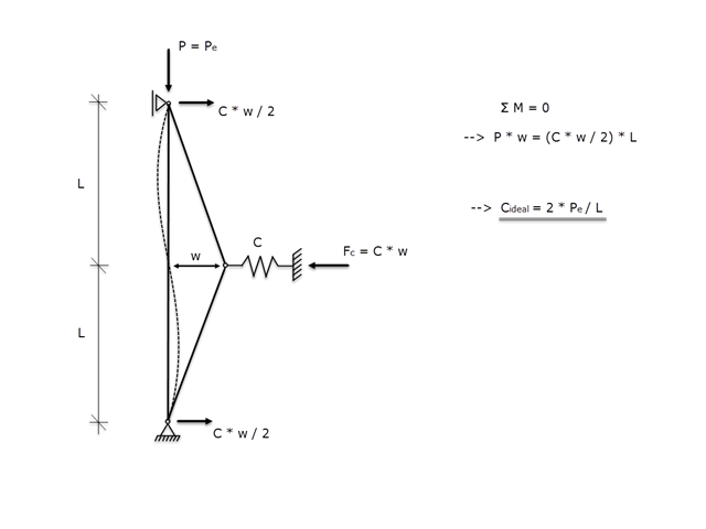
Jeżeli pręt posiada podparcie poprzeczne, zapobiegające wyboczeniu spowodowanemu przez ściskającą siłę osiową, należy upewnić się, że podpora boczna jest na tyle sztywna, aby rzeczywiście zapobiec wyboczeniu. Dlatego też celem niniejszego artykułu jest określenie idealnej sztywności sprężystej podpory bocznej z wykorzystaniem modelu Wintera.
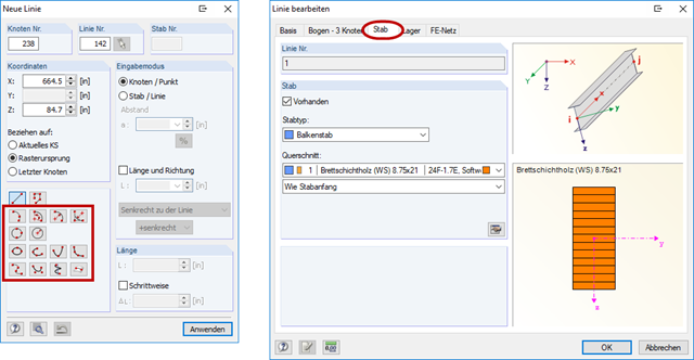
Program RFEM oferuje również możliwość modelowania belek zakrzywionych. Hierfür muss zunächst eine gekrümmte Linie erstellt werden (siehe Bild 01). Dieser Linie kann im Anschluss ein Stab mit einem Querschnitt zugeordnet werden. Die Vorteile gegenüber der Modellierung mit Stabsegmenten sind die einfachere Handhabung bei der Modellierung sowie die eindeutigere Ergebnisausgabe der Schnittgrößen.
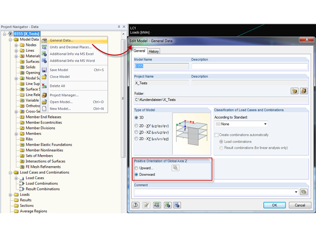
Vor Erstellung eines statischen Modells macht sich jeder Anwender Gedanken über die Randparameter des Systems und wie das Modell am besten abgebildet werden kann. Ein besonderes Augenmerk sollte hierbei auch auf die Orientierung des globalen Koordinatensystems gelegt werden. Im ingenieurtechnischen Bereich wird die globale Z-Achse in der Regel nach unten orientiert (in Richtung der Eigengewichtskraft), wobei sie im architektonischen Bereich meist nach oben ausgerichtet verläuft. Diese Unterschiede können oftmals zu Schwierigkeiten bei der Modellierung führen, beispielsweise beim Austausch von Gesamtmodellen oder DXF-Folien.
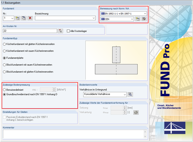
Oprócz wymiarowania betonu zbrojonego zgodnie z EN 1992-1-1, RF-/FOUNDATION Pro umożliwia przeprowadzanie obliczeń geotechnicznych zgodnie z EN 1997-1. W RF-/FOUNDATION Pro, wymiarowanie dopuszczalnego parcia gruntu jest przeprowadzane jako wymiarowanie odporności na zniszczenie gruntu. Wird als Nationaler Anhang CEN ausgewählt, stehen dem Anwender zwei Möglichkeiten für die Definition des Grundbruchwiderstandes zur Verfügung. Zum einen kann der zulässige charakteristische Wert der Sohlspannung σRk vom Benutzer direkt vorgegeben werden. Zum anderen besteht auch die Möglichkeit der analytischen Ermittlung der zulässigen Bodenpressung nach [1] Anhang D.
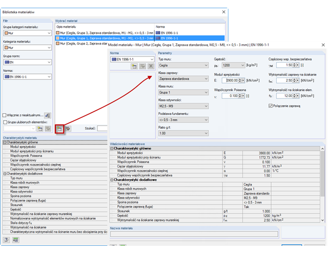
Aby za pomocą programu RFEM oszacować zachowanie konstrukcyjne muru w sposób zbliżony do rzeczywistości, należy najpierw wybrać materiał i model materiałowy. Da Mauerwerk auf Zug mit Rissbildung reagiert, muss hier ein nichtlineares Materialmodell verwendet werden, welches bei Vorhandensein des Zusatzmoduls RF-MAT NL selektiert werden kann.
Für die korrekte Modellierung und Berechnung von Schwimmkörpern (spezielle Flöße, Pontons, schwimmende Schiffsanleger, Schwimmbagger, Schwimmhäuser, Schwimminseln, Schwimmkrane, Wohnboote et cetera) ist eine zweistufige Berechnung notwendig.
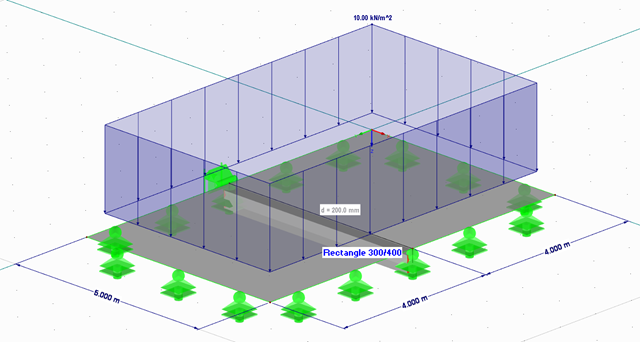
Dieser Beitrag beschreibt, wie eine Flachdecke in RFEM als 2D-Modell erstellt und die Belastung nach Eurocode 1 aufgebracht wird. Die Lastfälle werden nach Eurocode 0 kombiniert und linear berechnet. Im Zusatzmodul RF-BETON Flächen erfolgt die Biegebemessung der Decke unter Berücksichtigung der Normvorgaben nach Eurocode 2. Die Bewehrung wird für Bereiche, die von der Matten-Grundbewehrung nicht abgedeckt sind, durch eine Stabstahlbewehrung ergänzt.
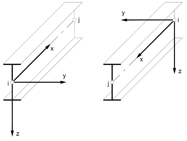
W konstrukcjach przestrzennych położenie pręta odgrywa ważną rolę w określaniu sił wewnętrznych. Die Ausrichtung der Stabachsen kann zum einen durch einen globalen Querschnittsdrehwinkel, zum anderen durch einen stabspezifischen Stabdrehwinkel definiert werden. Diese beiden Winkel werden addiert, um die Lage der Stab-Hauptachsen im 3D-Modell festzulegen.
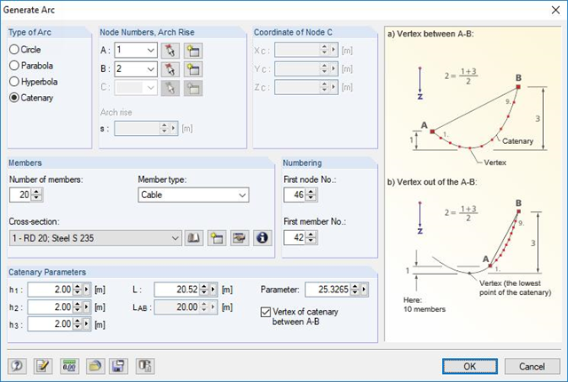
RFEM und RSTAB können als Vertreter der allgemeinen Stab- beziehungsweise FEM-Programme eine Vielzahl von Teilgebieten des Bauwesens abdecken. So ist auch die Bemessung von Seiltragwerken in beiden Software-Lösungen möglich. Im Folgenden sollen einige Modellierungs- und Bemessungshilfen vorgestellt werden.
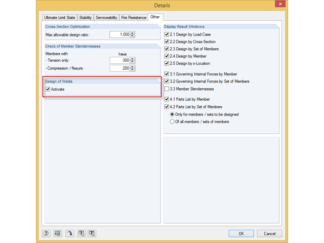
Das Zusatzmodul RF-/STAHL EC3 kann den Nachweis der Halskehlnähte für alle parametrischen, geschweißten Querschnitte der Querschnittsbibliothek führen. Hierzu muss die Option in den Detaileinstellungen des Moduls aktiviert werden. Alternativ kann auch ein Flächenmodell zur Bemessung genutzt werden.
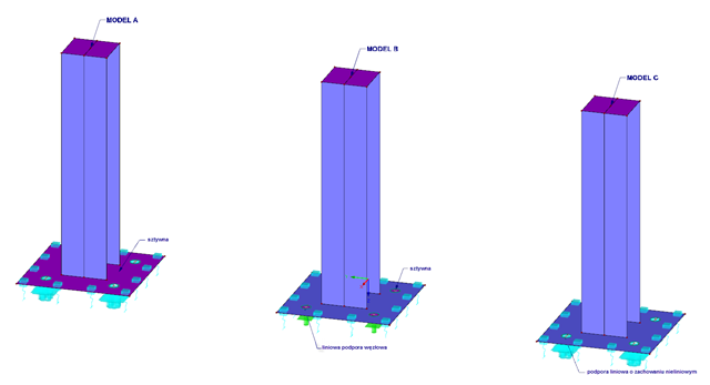
Podczas wymiarowania podstaw słupów, często stosowane są kotwy o wysokiej wytrzymałości. In diesem Beispiel soll die Abbildung mit verschiedenen Modellen für einen Stützenfuß und deren Auswertung erläutert werden.
Konstrukcje różnie reagują na działanie wiatru, w zależności od sztywności, masy i tłumienia. Zasadniczo rozróżnia się budynki, które są podatne na drgania oraz takie, które nie są na nie podatne.
![Układ konstrukcyjny i wymiary przekroju według [1]](/pl/webimage/009153/482068/01-de.png?mw=640&hash=9f6ca6566391e0348354d64018782d9ffd5f7c70)
Istnieje kilka opcji obliczania półsztywnej belki zespolonej. Opcje te różnią się głównie sposobem modelowania. Podczas gdy metoda Gamma zapewnia proste modelowanie, w przypadku stosowania innych metod (np. analogia ścinania) do modelowania wymagane są dodatkowe nakłady pracy, które są jednak równoważone przez znacznie bardziej elastyczne zastosowanie w porównaniu z metodą Gamma.

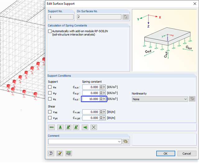
Bei der Modellierung von Bohrpfählen bieten RFEM und RSTAB verschiedene Optionen. Auf der einen Seite lassen sich Bohrpfähle als einwertige Auflager beziehungsweise Pendelstützen darstellen. Auf der anderen Seite ist ebenso eine realistische Modellierung unter Berücksichtigung des Baugrundes mit Hilfe des Ansatzes einer Stabbettung möglich. Im Folgenden werden diesbezüglich zwei Beispiele veranschaulicht. Die Thematiken Pfahlspitzenwiderstand, Pfahlmantelreibung und Bodenschichten sind hingegen kein Bestandteil dieses Beitrages.
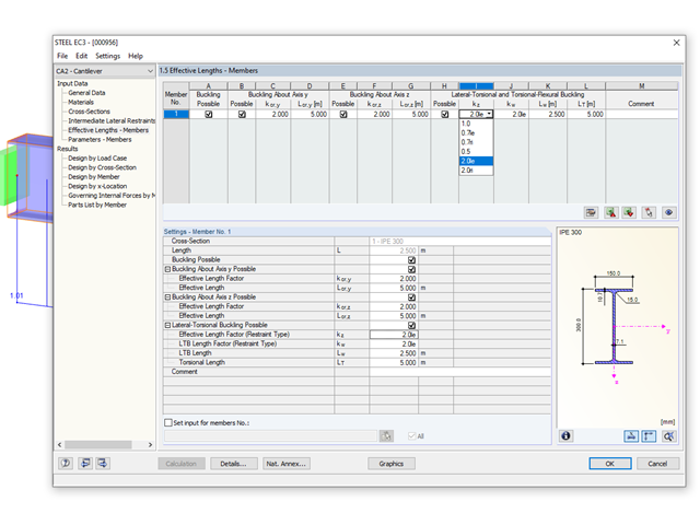
Die Stab-Randbedingungen beeinflussen das ideale Verzweigungsmoment bei Biegedrillknicken Mcr in entscheidender Weise. Für die Ermittlung wird im Programm ein ebenes Modell mit vier Freiheitsgraden verwendet. Die entsprechenden Beiwerte kz und kw können hierbei für normkonforme Querschnitte individuell definiert werden. Damit lassen sich die Freiheitsgrade beschreiben, die durch die Lagerungsbedingungen an den beiden Stabenden vorliegen.
Bei Kontrollrechnungen und Vergleich der Schnittgrößen und der daraus resultierenden erforderlichen Bewehrung von Unterzügen tauchen teilweise große Unterschiede auf. Obwohl dieselben Lastannahmen und Stützweiten angesetzt werden, geben einige Programme beziehungsweise die Handrechnung stark abweichende Schnittgrößen gegenüber dem FEM-Modell aus. Die Unterschiede treten auch bereits beim zentrischen Stab auf und ohne Berücksichtigung der Schnittgrößenanteile aus den gegebenenfalls mitwirkenden Plattenbreiten.