24 Wyniki
Wyświetl wyniki:
Sortuj według:
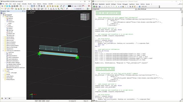
Webservice to komunikacja między maszynami i programami. Komunikacja ta odbywa się za pośrednictwem sieci i dlatego może być wykorzystywana przez dowolny program, który może wysyłać i odbierać ciągi znaków za pośrednictwem protokołu HTTP. Programy RFEM 6 i RSTAB 9 zapewniają interfejs oparty na tych wieloplatformowych usługach sieciowych. Ten tutorial pokazuje podstawy korzystania z języka programowania VBA.
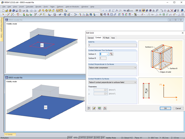
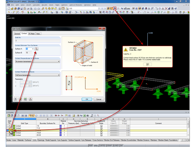
Die Kontakteigenschaften zwischen zwei Flächen können in RFEM mit Hilfe von Kontaktvolumen abgebildet werden. Bei der Modellierung ist unter anderem zu beachten, dass in der Regel beide Kontaktflächen eines Kontaktvolumens die gleichen integrierten Objekte aufweisen sollten. Es empfiehlt sich daher, gleich bei der Anlage der Kontaktflächen die zweite Kontaktfläche durch Kopieren zu erstellen.
Die Kontakteigenschaften zwischen zwei Flächen können in RFEM mit Hilfe von Kontaktvolumen abgebildet werden.
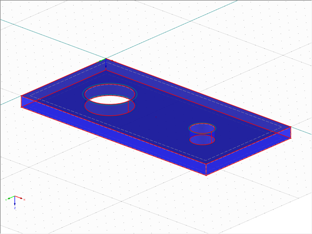
Das Einfügen von Löchern in Flächen ist durch eine große Auswahl an Werkzeugen sehr einfach. Um bei Volumen Löcher oder Bohren einzufügen, ist zu beachten, dass bei einem durchgehendem Loch am Anfang und am Ende eine Öffnung erstellt werden muss und zudem eine Fläche, welche das Loch von dem Volumen abtrennt.
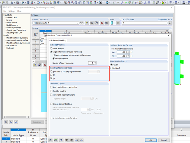
Bei der Glasbemessung im Zusatzmodul RF-GLAS stehen grundsätzlich zwei verschiedene Berechnungsoptionen zur Verfügung: eine 2D- und eine 3D-Berechnung. Grundsätzlicher Unterschied dieser beiden Bemessungsvarianten ist die vom Programm automatisierte Modellierung der Scheiben im temporären Modell. Bei einer 2D-Bemessung werden für die einzelnen Scheiben gängige Flächenelemente (Plattentheorie) generiert, während bei der 3D-Bemessung die einzelnen Scheiben als Volumen abgebildet werden. Je nach gewähltem Schichtaufbau steht die Option zur Wahl oder wird vom Programm bereits automatisch vorgegeben.
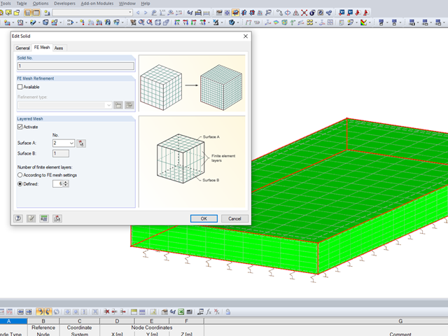
Bei Volumenkörpern besteht eine weitere Option der FE-Netz-Einstellung. Es ist möglich, neben einer ganzheitlichen FE-Netzverdichtung ein geschichtetes FE-Netz anzuordnen. W tym celu można wykonać określony podział bryły z elementami ES pomiędzy dwiema równoległymi powierzchniami. Diese Option eignet sich speziell für sehr ausgedehnte Volumen-Geometrien mit geringer Höhe.
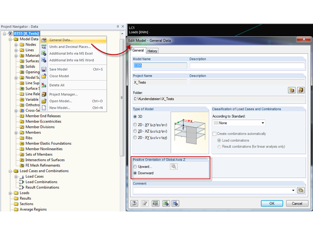
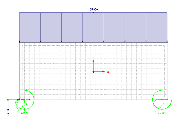
Vor Erstellung eines statischen Modells macht sich jeder Anwender Gedanken über die Randparameter des Systems und wie das Modell am besten abgebildet werden kann. Ein besonderes Augenmerk sollte hierbei auch auf die Orientierung des globalen Koordinatensystems gelegt werden. Im ingenieurtechnischen Bereich wird die globale Z-Achse in der Regel nach unten orientiert (in Richtung der Eigengewichtskraft), wobei sie im architektonischen Bereich meist nach oben ausgerichtet verläuft. Diese Unterschiede können oftmals zu Schwierigkeiten bei der Modellierung führen, beispielsweise beim Austausch von Gesamtmodellen oder DXF-Folien.
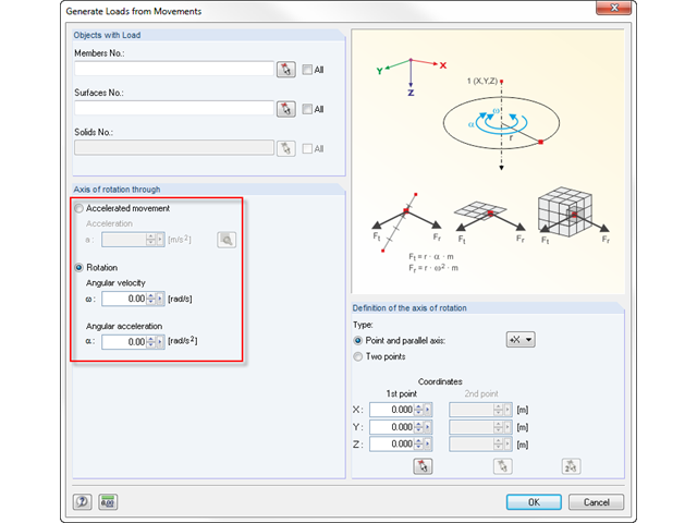
Mit RFEM lassen sich Stab- Flächen- oder Volumenlasten resultierend aus Bewegungen generieren. Somit können beispielsweise Brems- oder Beschleunigungskräfte aus geradlinigen Bewegungen oder aus Drehbewegungen am System automatisch generiert werden.
Durch einen Doppelklick auf die Elementnummern (erste Spalte) der Tabellen, wird das zugehörige Dialogfenster aufgerufen.
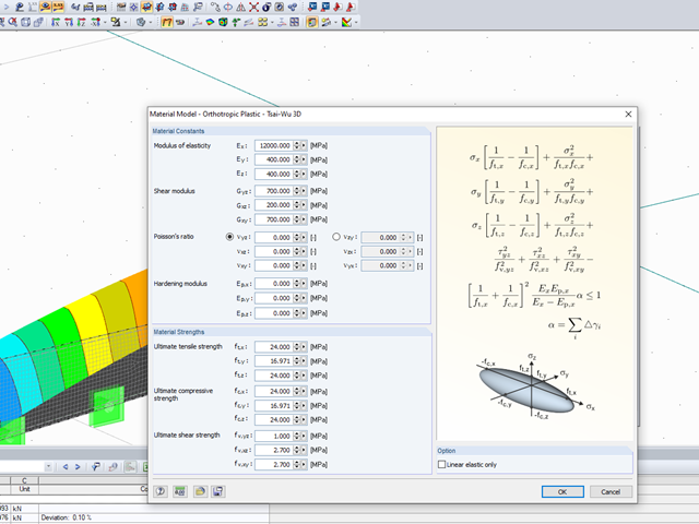
Mit dem orthotropen elastisch-plastischen Materialmodell können in RFEM 5 Volumen mit plastischen Materialeigenschaften berechnet und nach dem sogenannten Tsai-Wu-Kriterium ausgewertet werden. Das Tsai-Wu-Kriterium geht auf Stephen W. Tsai und Edward M. Wu zurück, die es 1971 für ebene Spannungszustände veröffentlichten.
Mit dem elastisch-plastischen Materialmodell haben Sie in RFEM 5 die Möglichkeit, Flächen und Volumen mit plastischen Materialeigenschaften zu berechnen und eine Spannungsauswertung durchzuführen. Dieses Materialmodell basiert auf der klassischen Von-Mises-Plastizität.
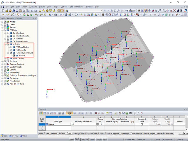
Każda bryła posiada lokalny układ współrzędnych. Auch die Spannungen und Verzerrungen sind auf dieses lokale Achsensystem bezogen.
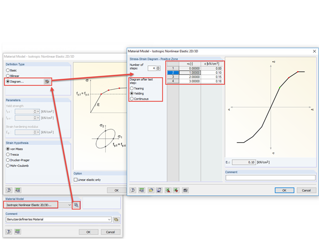
Mit dem nichtlinear-elastischen Materialmodell können in RFEM 5 Flächen und Volumen mit nichtlinearen Materialeigenschaften berechnet und eine Spannungsauswertung durchgeführt werden.
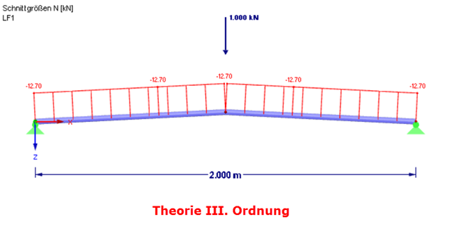
Wenn die Berechnung eines Stabmodells nach Theorie II. Ordnung mit einer Fehlermeldung endet, liegt die Ursache dieser Instabilität nicht selten an ausgefallenen Zugstäben: Sobald in einem Berechnungsschritt Druckkräfte in einem Zugstab auftreten, wird dieser Stab in den folgenden Iterationen nicht mehr berücksichtigt. Dadurch kann das Modell instabil werden.
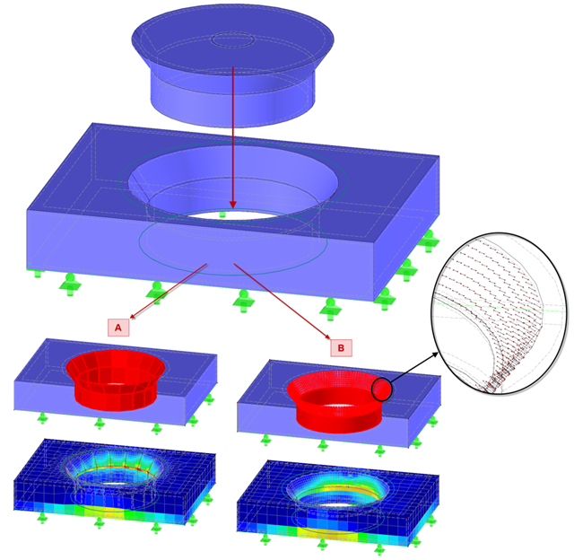
Für detailliertere Untersuchungen von Scher-Lochleibungs-Verbindungen beziehungsweise deren unmittelbarer Umgebung spielt die Vorgabe der nichtlinearen Kontaktproblematik eine wichtige Rolle. In diesem Beitrag wird mithilfe eines Volumenmodells nach vergleichbaren und vereinfachten Flächenmodellen gesucht.
Das Schalenbeulen gilt als das jüngste und am wenigsten erforschte Stabilitätsproblem der Bautechnik. Dies liegt weniger an mangelnden Forschungsaufwendungen, sondern vielmehr an der Komplexität der Theorie. Mit der Einführung und Fortentwicklung der Finite-Elemente-Methode in der bautechnischen Praxis erscheint es manchem Ingenieur nicht mehr erforderlich, sich mit der komplizierten Theorie des Schalenbeulens auseinanderzusetzen. Zu welchen Problemen und Fehlern dies führen kann, ist in [1] sehr gut zusammengefasst.
Modelltechnisch besteht ein ideales Gas aus frei schwirrenden ausdehnungslosen Masseteilchen in einem Volumenraum. In diesem Raum bewegt sich jedes Teilchen mit einer Geschwindigkeit in eine Richtung. Der Stoß eines Teilchens an ein anderes Teilchen oder die Volumenbegrenzungen führt zu einer Ablenkung und Veränderung der Geschwindigkeit der Beteiligten.
W przypadku konstrukcji płytowych zawsze należy uwzględnić realistyczne warunki podparcia definicji. Je nachdem, in welcher Art und Weise die Nachgiebigkeit der Lagerung definiert wird, ergeben sich zum Teil deutliche Unterschiede in den Ergebnissen.
W przypadku uszkodzenia postkrytycznego następuje istotna zmiana geometrii konstrukcji. Nach dem Erreichen der Instabilität des Gleichgewichts wird wieder eine stabile, tragfähige Lage erreicht. Analiza postkrytyczna wymaga podejścia "eksperymentalnego". Obciążenie w takim przypadku należy zwiększać stopniowo.
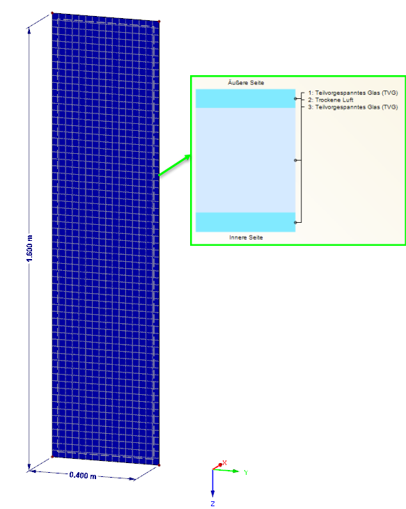
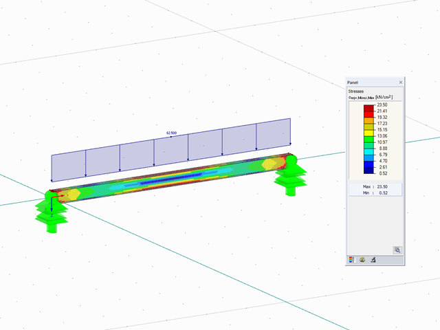
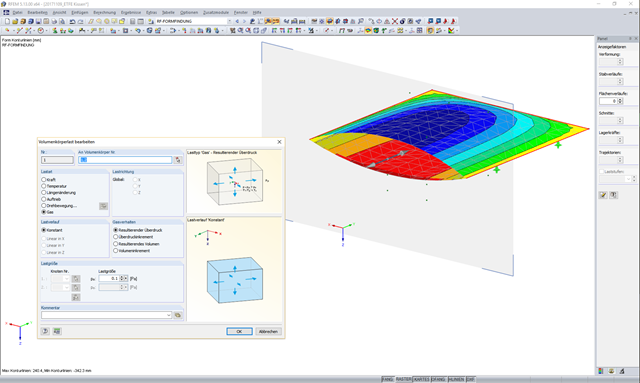
Obciążenie tafli szkła izolacyjnego spowodowane wpływami klimatycznymi jest wyraźnie uregulowane w normie DIN 18008. Diese Art der Belastung kann bei entsprechender Scheibengeometrie auch maßgebend für die Bemessung im Zustand der Tragfähigkeit werden. Eine FE-Bemessung am Gesamtsystem mit Abbildung des SZR als Gasvolumen liefert exakte Ergebnisse zur Analyse. Im Gegenzug gewinnt jedoch auch eine stichpunktartige Plausibilitätskontrolle immer mehr an Bedeutung. Nachfolgend werden verschiedene Optionen aufgezeigt, wie diese Kontrollen durchgeführt werden können.
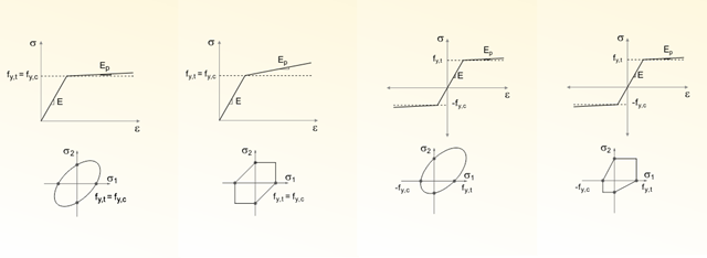
Jeden z moich wcześniejszych artykułów opisał model materiałowy Izotropowy nieliniowo sprężysty. Viele Materialien besitzen aber kein rein symmetrisches nichtlineares Materialverhalten. Auch die in dem Beitrag erwähnten Fließgesetze nach von Mises, Drucker-Prager und Mohr-Coulomb sind in dieser Hinsicht auf die Fließfläche im Hauptspannungsraum beschränkt.
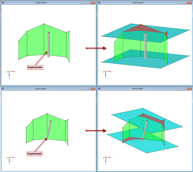
Seit der Freigabe von RFEM 5 steht der Stabtyp "Ergebnisstab" zur Verfügung. Der Ergebnisstab ist ein virtueller Stab ohne jegliche Steifigkeit und benötigt keine Lagerung. Er kann vielseitig eingesetzt werden, um Ergebnisse aus Stäben, Flächen und Volumen aufzuintegrieren und als Stabschnittgrößen auszugeben.
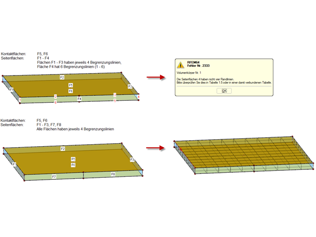
Bryły kontaktowe można tworzyć pomiędzy dwiema powierzchniami płaskimi lub pomiędzy dwiema powłokami cylindrycznymi. Ist jedoch der Bereich des Kontaktproblems etwas komplizierter, muss entweder das System so vereinfacht werden, dass die Anforderungen eines Kontaktvolumens erreicht werden, oder man greift auf die "alte" Modellierungsart mittels Stäbchenmodell zurück.
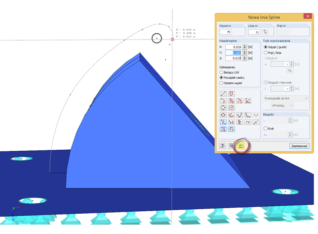
Aby wyświetlić zakrzywioną geometrię (najlepiej w linii ciągłej), w programie RFEM można zastosować na przykład splajny lub NURBS. Beim Modellieren müssen nun die einzelnen Knoten nacheinander gepickt werden. Unterläuft einem hier ein Fehler, kann dieser mit der speziellen UnDo-Funktion im Linien-Fenster rückgängig gemacht werden. Es ist somit nicht erforderliche, den kompletten Linienzug erneut einzugeben.