392 Wyniki
Wyświetl wyniki:
Sortuj według:

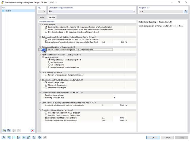
Analiza wyboczenia giętnego jest połączeniem analizy stateczności i stanu granicznego nośności, stosowana w konstrukcjach stalowych od setek lat. Punktem wyjścia do rozważenia kwestii stateczności jest krytyczne obciążenie wyboczeniowe, ale dotychczas nie przeprowadzono obliczeń bez uwzględnienia imperfekcji. Jak dokładnie określane są te imperfekcje?

Podczas obliczania siły tnącej w programie Wymiarowanie betonu zbrojonego, działającą siłę tnącą Vz można zredukować zgodnie z EN 1992-1-1. Poniższy artykuł opisuje redukcję siły tnącej od obciążeń skupionych w pobliżu podpory oraz wymiarowanie sił tnących w odległości d od krawędzi podpory w przypadku obciążenia równomiernie rozłożonego.

Każdego dnia tysiące inżynierów konstrukcyjnych projektują elementy konstrukcyjne, korzystając z wzorów kontroli projektu, uwzględniających krytyczne obciążenie wyboczeniowe. Ale skąd wzięły się te starożytne wzory, które opracował ponad 200 lat temu i które stanowią podstawę wszystkich trzech koncepcji projektowania konstrukcji stalowych?

W tym artykule pokażemy, jak zdefiniować żebra podłużne na blasze pręta za pomocą komponentu „Żebro” w rozszerzeniu Połączenia stalowe.

Z tego artykułu dowiesz się, jak zamodelować proste połączenie z blachą czołową w programie RFEM 6.
![Podstawowe kształty konstrukcji membranowych [1]](/pl/webimage/009595/2419506/01-png.png?mw=640&hash=8a9ac87bf3acfb73e6cad970f55eb968a841595c)
Niniejszy artykuł skupia się na specyficznych aspektach projektowania konstrukcji membranowych, które mają specyficzne wymagania, takich jak znajdowanie kształtu (form-finding) i generowanie szablonów cięcia. Integralną częścią projektowania tych konstrukcji jest proces wyszukiwania odpowiednich wstępnie sprężonych kształtów i generowania szablonów cięcia. Tekst krótko opisuje dwa podstawowe procesy w projektowaniu konstrukcji membranowych. Celem jest zilustrowanie ich fizycznego charakteru i zademonstrowanie poszczególnych stwierdzeń za pomocą towarzyszących im przykładów.

Zrozumienie sztywności połączeń stalowych ma kluczowe znaczenie w projektowaniu konstrukcji. Często połączenia są traktowane jako połączenia całkowicie sztywne lub przegubowe, co może prowadzić do nieekonomicznych lub nawet ryzykownych warunków projektowych. Dowiedz się, w jaki sposób program RFEM firmy Dlubal i rozszerzenie Połączenia stalowe pomagają weryfikować sztywność połączeń i nośność na zginanie, zapewniając bezpieczniejsze i bardziej ekonomiczne warunki projektowe.
Ten artykuł opisuje i wyjaśnia wpływ sztywności na zginanie kabli na ich siły wewnętrzne. Z tego artykułu dowiesz się również, jak zredukować ten wpływ.

W artykule przedstawiono podstawowe pojęcia z zakresu dynamiki konstrukcji i ich roli w projektowaniu konstrukcji sejsmicznych. Duży nacisk kładzie się na wyjaśnienie aspektów technicznych w zrozumiały sposób, aby tematyka była zrozumiała dla czytelników bez dużej wiedzy technicznej.

Wyboczenie giętno-skrętne (LTB) jest zjawiskiem, które występuje, gdy belka lub element konstrukcyjny są zginane, a pas ściskany nie jest wystarczająco podparty bocznie. Prowadzi to do kombinacji przemieszczenia bocznego i skręcenia. Jest to decydujący czynnik przy wymiarowaniu elementów konstrukcyjnych, zwłaszcza smukłych belek i dźwigarów.

W rozszerzeniu Projektowanie konstrukcji stalowych dla programu RFEM 6 dostępne są trzy typy ram sprężystych (zwykłe, pośrednie i specjalne). Wyniki obliczeń sejsmicznych zgodnie z AISC 341-22 są podzielone na dwie sekcje: wymagania dotyczące prętów i połączeń.
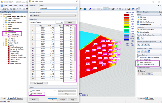
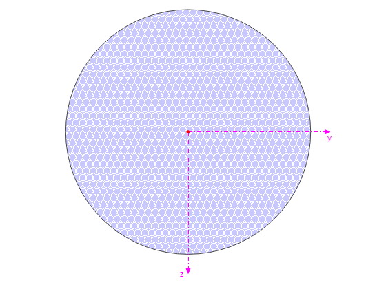
Za pomocą programów RWIND 2 i RFEM 6 można teraz obliczać obciążenia wiatrem na podstawie zmierzonego eksperymentalnie ciśnienia wiatru na powierzchnie. Zasadniczo dostępne są dwie metody interpolacji, umożliwiające rozłożenie ciśnienia mierzonego w izolowanych punktach na powierzchnie. Żądany rozkład ciśnienia można uzyskać za pomocą odpowiedniej metody i ustawień parametrów.

Rozszerzenie Projektowanie konstrukcji stalowych w RFEM 6 oferuje teraz możliwość przeprowadzania obliczeń sejsmicznych zgodnie z AISC 341-16 i AISC 341-22. Obecnie dostępnych jest pięć typów systemów sejsmicznych (SFRS).

W rozszerzeniu Projektowanie konstrukcji stalowych dla programu RFEM 6 dostępne są trzy typy ram sprężystych (zwykłe, pośrednie i specjalne). Wyniki obliczeń sejsmicznych zgodnie z AISC 341-16 są podzielone na dwie sekcje: wymagania dotyczące prętów i połączeń.

Obliczanie ramy momentowej zgodnie z AISC 341-16 jest teraz możliwe w rozszerzeniu Projektowanie konstrukcji stalowych dla programu RFEM 6. Wynik obliczeń sejsmicznych jest podzielony na dwie sekcje: wymagania dotyczące prętów i połączeń. W tym artykule omówiono wymaganą wytrzymałość połączenia. Przedstawiono przykładowe porównanie wyników pomiędzy RFEM a AISC Seismic Design Manual.

Obliczenia zwykłej ramy stężonej koncentrycznie (OCBF) oraz SCBF (specjalnej konstrukcji szkieletowej stężonej koncentrycznie) można przeprowadzić w rozszerzeniu Projektowanie konstrukcji stalowych dla programu RFEM 6. Wyniki obliczeń sejsmicznych zgodnie z AISC 341-16 i 341-22 są podzielone na dwie sekcje: Wymagania dotyczące prętów i połączeń.
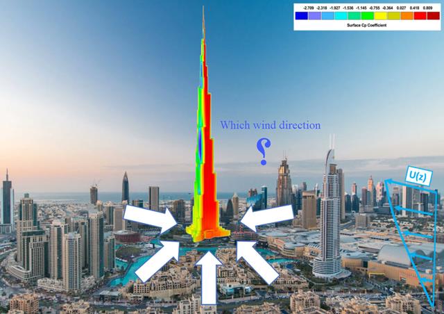
Kierunek wiatru odgrywa kluczową rolę w kształtowaniu wyników symulacji komputerowej mechaniki płynów (CFD) oraz w projektowaniu konstrukcyjnym budynków i infrastruktury. Jest to decydujący czynnik w ocenie interakcji sił wiatru z konstrukcjami, wpływających na rozkład ciśnienia wiatru, a w konsekwencji na reakcje konstrukcji.
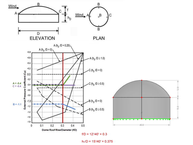
Jeśli chodzi o obciążenia wiatrem konstrukcje budowlane zgodnie z ASCE 7, można znaleźć wiele źródeł, które mogą uzupełnić normy projektowe i pomóc inżynierom w zastosowaniu obciążeń poprzecznych. Jednak inżynierom może być trudniej znaleźć podobne zasoby dla obciążeń wiatrem na konstrukcjach innych niż budynki. W tym artykule omówiono etapy obliczania i przykładania obciążeń wiatrem zgodnie z ASCE 7-22 na okrągłym zbiorniku żelbetowym z dachem w kształcie kopuły.
![Rozpiętości na podstawie Rysunku 5.2 z [1]](/pl/webimage/039540/3493372/01_Abmessungen_EN.png?mw=640&hash=a3c436931baff3514db261b2d11bfa39abae9170)
Aby poprawnie zwymiarować dźwigar lub belkę teową w programie RFEM 6 i w module dodatkowym 'Wymiarowanie betonu', ważne jest określenie 'szerokości pasów' prętów żebrowych. W tym artykule omówiono opcje wprowadzania danych dla belki dwuprzęsłowej oraz obliczanie wymiarów pasów zgodnie z EN 1992-1-1.
Ten przykład pokazuje, jak szybko określić w programie RFEM wyporność lub stan graniczny wyporności dla kontenera.
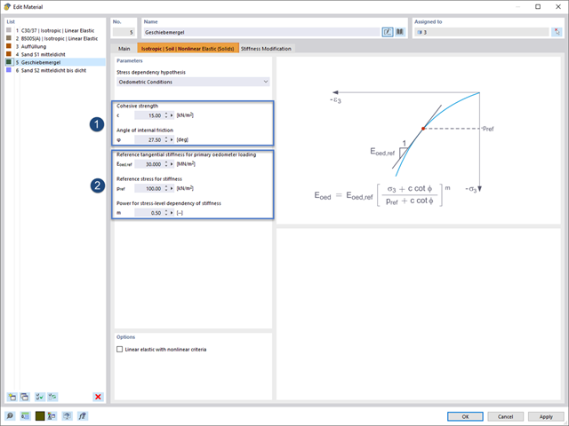
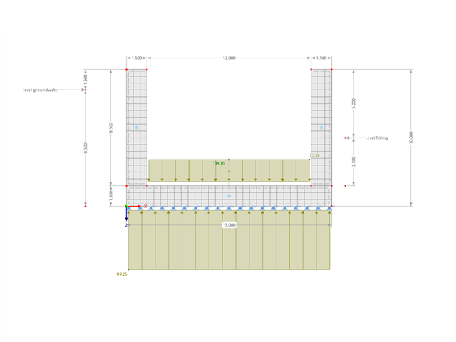
Rozszerzenie Analiza geotechniczna zapewnia programowi RFEM dodatkowe specyficzne modele materiałowe podłoża, które mogą odpowiednio odwzorować złożone zachowanie materiału podłoża. W tym artykule zaprezentujemy, w jaki sposób można określić zależną od naprężeń sztywność modeli materiałowych gruntu.

Zarówno analiza drgań własnych, jak i analiza spektrum odpowiedzi przeprowadzane są na układzie liniowym. Jeżeli w modelu występują nieliniowości, podlega on linearyzacji, dzięki czemu elementy nieliniowe nie są brane pod uwagę w dalszej analizie. Mogą to być na przykład pręty rozciągane, podpory nieliniowe lub przeguby nieliniowe. W tym artykule pokazano, w jaki sposób można nimi zarządzać w analizie dynamicznej.
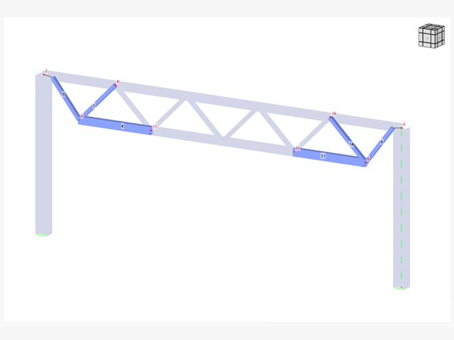
W wielu konstrukcjach szkieletowych zastosowanie prostego pręta nie jest już wystarczające. Często należy wziąć pod uwagę osłabienia przekroju lub otwory w belkach betonowych. Dla takich zastosowań dostępny jest typ pręta "Model powierzchniowy". Można go można zintegrować z modelem jak w przypadku każdego innego pręta i oferuje on wszystkie opcje modelu powierzchniowego. Ten artykuł techniczny pokazuje zastosowanie pręta typu Model powierzchniowy w istniejącym układzie konstrukcyjnym i opisuje integrację otworów pręta.
Jeżeli na górnej półce znajduje się płyta betonowa, działa ona jak podpora boczna (konstrukcja zespolona) i zapobiega problemom ze statecznością przy wyboczeniu skrętnym. Jeżeli moment zginający jest ujemny, dolna półka jest obciążona, a górna rozciągana. Jeżeli podparcie boczne nie jest wystarczające ze względu na sztywność środnika, kąt pomiędzy dolną półką a linią nacięcia środnika jest zmienny, przez co istnieje możliwość wystąpienia niestateczności wymiarowej dolnej półki.
Połączenia stalowe w programie RFEM 6 można tworzyć poprzez wprowadzenie wstępnie zdefiniowanych komponentów w rozszerzeniu Połączenia stalowe. Lista tych elementów jest stale rozszerzana, aby ułatwić modelowanie połączeń stalowych. W tym artykule przedstawiamy blachę łączącą, która została niedawno dodana do biblioteki rozszerzenia.
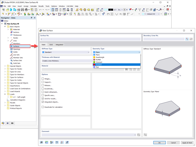
Powierzchnie w modelach budynków mogą mieć różne rozmiary i kształty. W programie RFEM 6 można uwzględnić wszystkie powierzchnie, ponieważ program umożliwia definiowanie różnych materiałów i grubości, a także powierzchni o różnej sztywności i typie geometrii. W tym artykule skupiono się na czterech z następujących typów powierzchni: obrócony, przycięty, bez grubości i przeniesienia obciążenia.
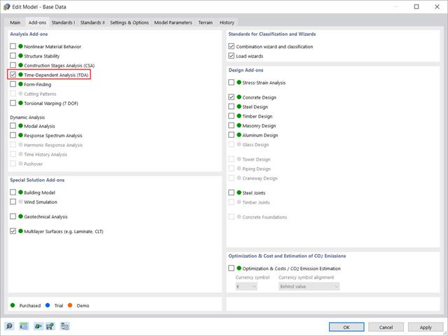
W tym artykule pokazano, w jaki sposób rozszerzenie „Analiza zależna od czasu” jest zintegrowane w programach RFEM 6 i RSTAB 9. Opisuje sposób definiowania danych wejściowych, takich jak charakterystyka materiału zależna od czasu, sposób określania typu analizy i czasy obciążenia.

Niniejszy artykuł jest związany z trwającym projektem, w ramach którego opracowywany i wdrażany jest cyfrowy bliźniak konstrukcyjny mostu Kalix w Szwecji.
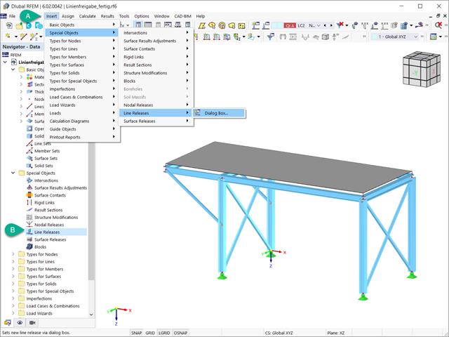
Zwolnienia liniowe to specjalne obiekty w programie RFEM 6, które umożliwiają rozdzielenie konstrukcyjne obiektów połączonych z linią. Stosowane są głównie do oddzielenia dwóch powierzchni, które nie są połączone sztywno lub przenoszą tylko siły ściskające na wspólnej linii granicznej. Poprzez definicję zwolnienia liniowego, w tym samym miejscu generowana jest nowa linia, przenosząca tylko zablokowane stopnie swobody. W niniejszym artykule przedstawiono definicję zwolnień liniowych na przykładzie praktycznym.

Osłony przeciwwiatrowe to specjalne konstrukcje tekstylne, które mają za zadanie chronić środowisko przed szkodliwymi cząsteczkami chemicznymi, jak również ograniczać erozję wietrzną, przyczyniając się do ochrony cennych zasobów. RFEM i RWIND są używane do analizy konstrukcji wiatrowej dla jednostronnej interakcji płyn-konstrukcja (FSI).
W tym artykule pokazano, jak wymiarować osłony przeciwwiatrowe przy użyciu programów RFEM i RWIND.
W tym artykule pokazano, jak wymiarować osłony przeciwwiatrowe przy użyciu programów RFEM i RWIND.