21 Wyniki
Wyświetl wyniki:
Sortuj według:

Ocena przemieszczenia kondygnacji w budynku jest kluczowa dla zapewnienia zadowalających parametrów konstrukcyjnych poprzez ograniczenie przemieszczenia kondygnacji. Nadmierne znoszenie może powodować niestateczność systemu i powodować uszkodzenia elementów niekonstrukcyjnych, takich jak ściany działowe. W tym artykule opisano procedurę wyznaczania przemieszczeń międzykondygnacyjnych zgodnie z ASCE 7-22 i rozszerzeniem Model budynku w programie RFEM 6.
Blachownica to ekonomiczny wybór w przypadku konstrukcji o dużych rozpiętościach. I-section steel plate girder typically has a deep web to maximize its shear capacity and flange separation, yet thin web to minimize the self-weight. Due to its large height-to-thickness (h/tw) ratio, transverse stiffeners may be required to stiffen the slender web.
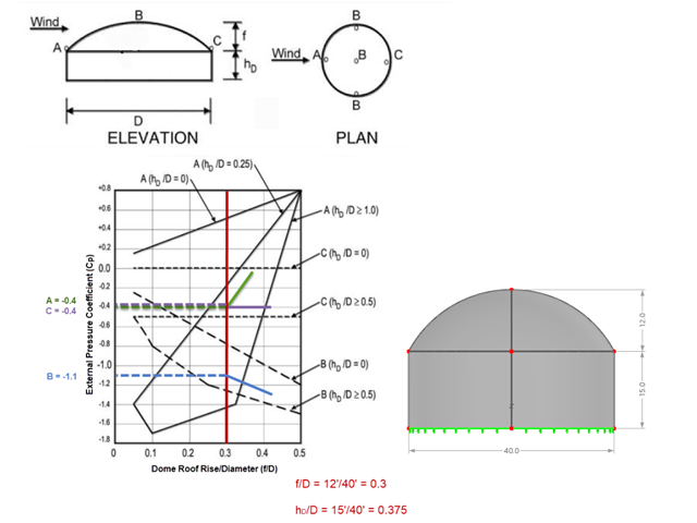
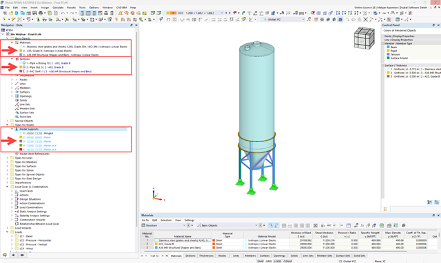
Jeśli chodzi o obciążenia wiatrem konstrukcje budowlane zgodnie z ASCE 7, można znaleźć wiele źródeł, które mogą uzupełnić normy projektowe i pomóc inżynierom w zastosowaniu obciążeń poprzecznych. Jednak inżynierom może być trudniej znaleźć podobne zasoby dla obciążeń wiatrem na konstrukcjach innych niż budynki. W tym artykule omówiono etapy obliczania i przykładania obciążeń wiatrem zgodnie z ASCE 7-22 na okrągłym zbiorniku żelbetowym z dachem w kształcie kopuły.
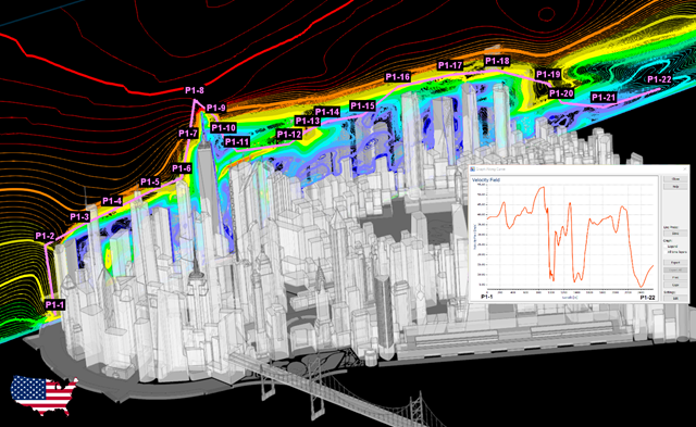
Zgodność z przepisami budowlanymi, takimi jak Eurokod, jest niezbędna dla zapewnienia bezpieczeństwa, integralności konstrukcji i trwałości budynków i konstrukcji. Obliczeniowa mechanika płynów (CFD) odgrywa istotną rolę w tym procesie, symulując zachowanie płynów, optymalizując projekty i pomagając architektom i inżynierom w spełnieniu wymagań Eurokodu związanych z analizą obciążenia wiatrem, wentylacją naturalną, bezpieczeństwem pożarowym i efektywnością energetyczną. Integrując CFD z procesem projektowania, profesjonaliści mogą tworzyć bezpieczniejsze, wydajniejsze i zgodne z przepisami budynki, które spełniają najwyższe standardy konstrukcyjne i projektowe w Europie.
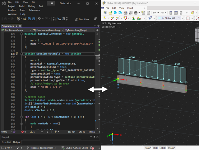
Nasza usługa sieciowa oferuje użytkownikom możliwość komunikacji z programami RFEM 6 i RSTAB 9 za pomocą różnych języków programowania. Funkcje wysokiego poziomu (HLF) firmy Dlubal umożliwiają rozszerzenie i uproszczenie funkcjonalności WebService. Zgodnie z RFEM 6 i RSTAB 9, korzystanie z naszego webservice sprawia, że praca inżyniera jest łatwiejsza i szybsza. Wypróbuj teraz! Ten samouczek pokazuje, jak korzystać z biblioteki C #na prostym przykładzie.
Celem zastosowania programów RFEM 6 i Blender z rozszerzeniem Bullet Constraints Builder jest uzyskanie graficznej reprezentacji zawalenia się modelu na podstawie rzeczywistych danych dotyczących właściwości fizycznych. Program RFEM 6 służy jako źródło geometrii i danych do symulacji. Jest to kolejny przykład, dlaczego ważne jest, aby nasze programy utrzymywać jako tak zwane BIM Open, aby umożliwić współpracę między różnymi dziedzinami oprogramowania.
Metoda CSA S16:19 Skutki stateczności w analizie sprężystej w Załączniku O.2 stanowi alternatywę dla metody Uproszczonej analizy stateczności z punktu 8.4.3. W tym artykule zostaną opisane wymagania załącznika O.2 i zastosowania w RFEM 6.
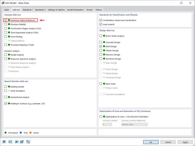
Rozszerzenie Nieliniowe zachowanie materiału umożliwia uwzględnienie nieliniowości materiałowych w programie RFEM 6. Ten artykuł zawiera przegląd dostępnych nieliniowych modeli materiałowych, które są dostępne po aktywowaniu tego rozszerzenia w danych bazowych modelu.
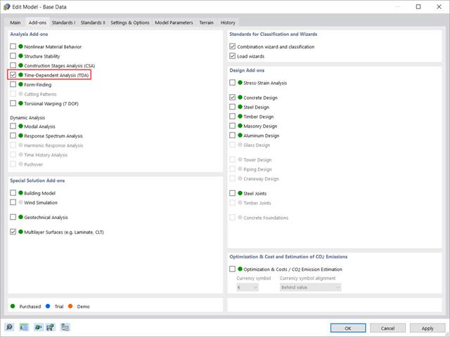
W tym artykule pokazano, w jaki sposób rozszerzenie „Analiza zależna od czasu” jest zintegrowane w programach RFEM 6 i RSTAB 9. Opisuje sposób definiowania danych wejściowych, takich jak charakterystyka materiału zależna od czasu, sposób określania typu analizy i czasy obciążenia.
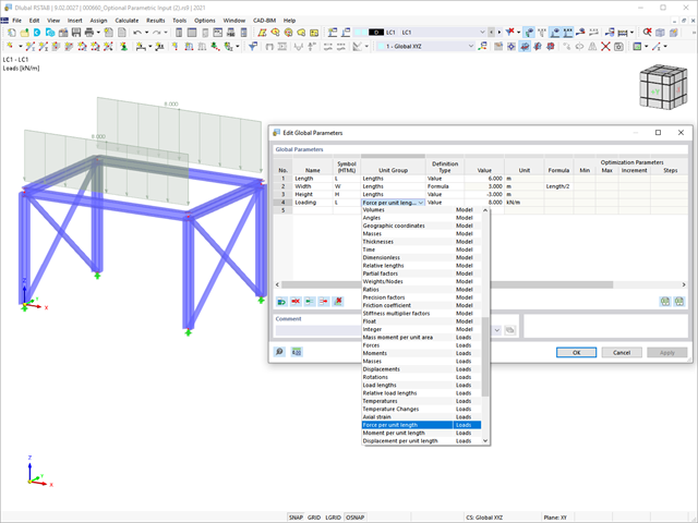
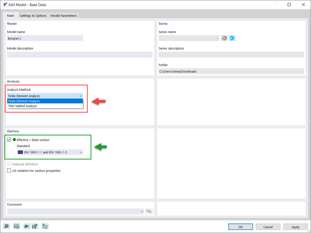
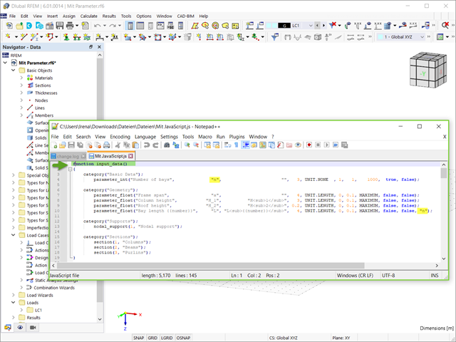
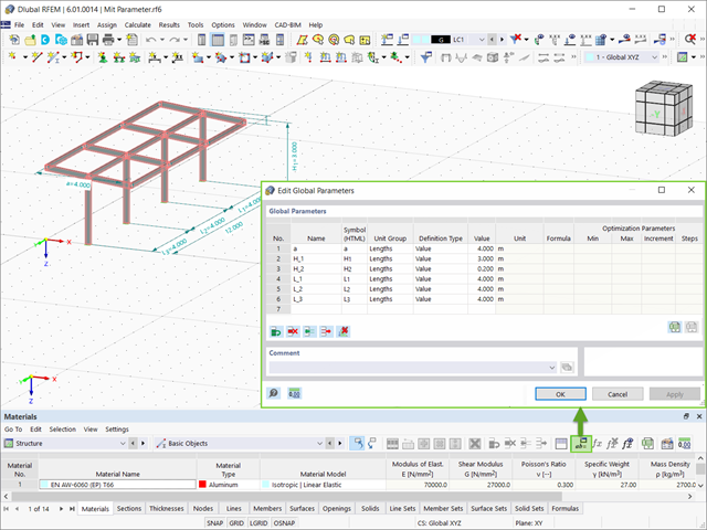
W tym artykule podsumowano zalety pracy ze sparametryzowanymi modelami w programach RFEM 6 i RSTAB 9.
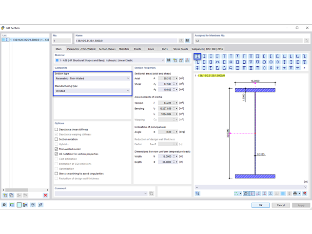
Samodzielny program RSECTION określa właściwości przekrojów cienkościennych i masywnych oraz przeprowadza analizę naprężeń. W poprzednim artykule z Bazy wiedzy zatytułowanym "Graficzne/tabelaryczne tworzenie przekrojów zdefiniowanych przez użytkownika w PRZEKRÓJ 1" omówiono podstawy definiowania przekrojów w programie. Z drugiej strony, ten artykuł jest podsumowaniem sposobu określania właściwości przekroju i przeprowadzania analizy naprężeń.

Zaletą modułu dodatkowego RFEM 6 Steel Joints jest możliwość analizy połączeń stalowych przy użyciu modelu MES, dla którego modelowanie przebiega w pełni automatycznie w tle. Elementy składowe złącza stalowego, które kontrolują modelowanie, można wprowadzić, definiując je ręcznie lub korzystając z dostępnych szablonów w bibliotece. Ta ostatnia metoda została opisana w poprzednim artykule z Bazy wiedzy zatytułowanym „Definiowanie komponentów połączenia stalowego przy użyciu biblioteki”. Definiowanie parametrów do wymiarowania połączeń stalowych jest tematem artykułu w bazie wiedzy „Projektowanie połączeń stalowych w RFEM 6”.

Rozszerzenie Projektowanie konstrukcji aluminiowych dla RFEM 6 wymiaruje pręty aluminiowe ze względu na stan graniczny nośności i użytkowalności zgodnie z Eurokodem 9. Ponadto możliwe jest wymiarowanie zgodnie z ADM 2020 (norma amerykańska).
Modele konstrukcji w programie RFEM 6 można zapisywać jako bloki i wykorzystywać ponownie w innych plikach programu RFEM. Zaletą bloków dynamicznych w porównaniu z blokami nie-dynamicznymi jest to, że umożliwiają interaktywną modyfikację parametrów konstrukcyjnych w wyniku modyfikowania zmiennych wejściowych. Jednym z przykładów jest możliwość dodawania elementów konstrukcyjnych poprzez zmianę tylko liczby przęseł jako zmiennej wejściowej. W tym artykule zademonstrowano taką funkcjonalność dla bloków dynamicznych tworzonych za pomocą skryptów.
Oprócz wstępnie zdefiniowanych modeli dostępnych jako bloki w Dlubal Center | Bloki, możliwe jest tworzenie nowych bloków i zapisywanie ich w sposób opisany w artykule z Bazy wiedzy "Zapisywanie modeli jako bloki w programie RFEM 6".
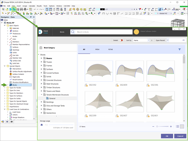
W programie RFEM 6 można zapisywać wybrane obiekty (a także całe konstrukcje) jako bloki i wykorzystywać je w innych modelach. Istnieją trzy typy bloków: bez parametrów, z parametrami i bloki dynamiczne (z wykorzystaniem JavaScript). W niniejszym artykule przedstawiono pierwszy typ bloku (bez parametrów).
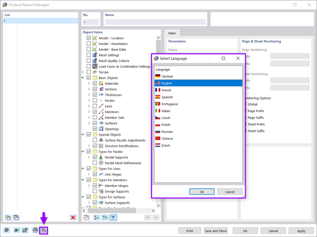
Wszystkie dane w programie RFEM 6 można udokumentować w wielojęzycznym raporcie. Protokół wydruku jest nowoczesny i zoptymalizowany w porównaniu z poprzednią generacją programu (RFEM 5). W tym artykule technicznym przedstawiono niektóre z najważniejszych funkcji.
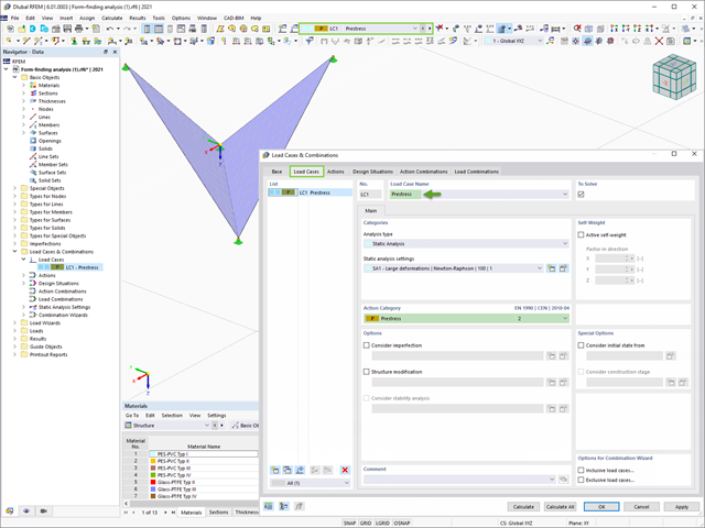
Program RFEM 6 zawiera rozszerzenie Form-Finding do określania kształtów równowagi modeli powierzchni obciążonych rozciąganiem i prętów obciążonych siłami osiowymi. Aktywuj ten dodatek w Danych bazowych modelu i użyj go, aby znaleźć położenie geometryczne, w którym naprężenie wstępne lekkich konstrukcji jest w równowadze z istniejącymi warunkami brzegowymi.
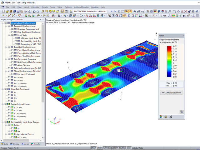
Moduł RF-CONCRETE Surfaces umożliwia wymiarowanie powierzchni z betonu zbrojonego (ściany, stropy, płyty fundamentowe) zgodnie z ACI 318-19 lub CSA A23.3-19. Powszechnym podejściem przy wymiarowaniu płyt jest zastosowanie pasm obliczeniowych do określenia średnich sił wewnętrznych w danym kierunku na szerokości pasma. Metoda ta sprowadza się zasadniczo do analizy elementu dwukierunkowo zbrojonego jako wydzielonych elementów jednokierunkowo zbrojonych, aby określić wymagane zbrojenie wzdłuż danego pasma.
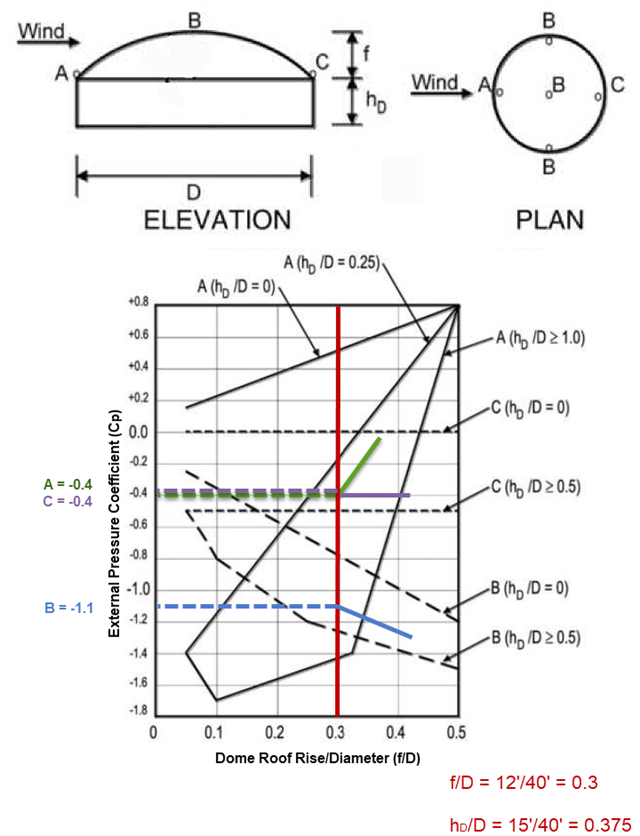
Jeśli chodzi o obciążenia wiatrem konstrukcje budowlane zgodnie z ASCE 7, można znaleźć wiele źródeł, które mogą uzupełnić normy projektowe i pomóc inżynierom w zastosowaniu obciążeń poprzecznych. However, engineers may find it more difficult to find similar resources for wind loading on non-building type structures. This article will examine the steps to calculate and apply wind loads as per ASCE 7-16 on a circular reinforced concrete tank with a dome roof.
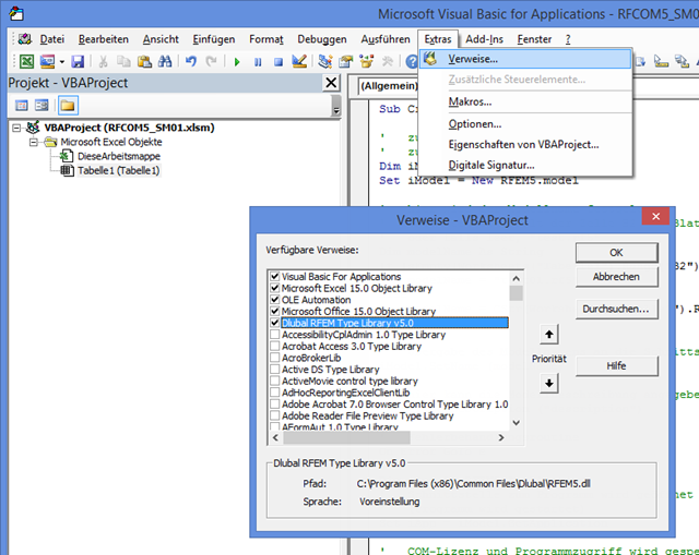
Pierwsza część postu na temat interfejsu COM opisuje otwieranie i zamykanie programu RFEM. Als Programmiersprache wird VBA in Excel verwendet, der Programmablauf ist aber identisch zur Programmierung mit C#. Damit VBA die Befehle zur Schnittstelle kennt, muss zunächst der entsprechende Verweis hinzugefügt werden. In der Abbildung ist links das Beispiel anhand von RFEM 5 zu sehen.