79 Wyniki
Wyświetl wyniki:
Sortuj według:

Analiza wyboczenia giętnego jest połączeniem analizy stateczności i stanu granicznego nośności, stosowana w konstrukcjach stalowych od setek lat. Punktem wyjścia do rozważenia kwestii stateczności jest krytyczne obciążenie wyboczeniowe, ale dotychczas nie przeprowadzono obliczeń bez uwzględnienia imperfekcji. Jak dokładnie określane są te imperfekcje?

Z tego artykułu dowiesz się, jak zamodelować proste połączenie z blachą czołową w programie RFEM 6.

Wyboczenie giętno-skrętne (LTB) jest zjawiskiem, które występuje, gdy belka lub element konstrukcyjny są zginane, a pas ściskany nie jest wystarczająco podparty bocznie. Prowadzi to do kombinacji przemieszczenia bocznego i skręcenia. Jest to decydujący czynnik przy wymiarowaniu elementów konstrukcyjnych, zwłaszcza smukłych belek i dźwigarów.
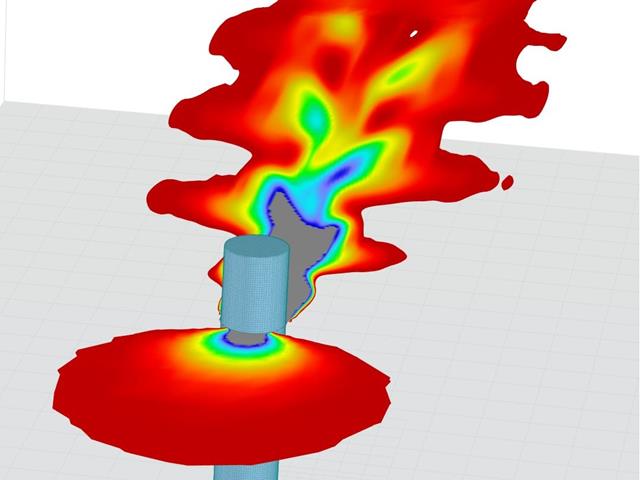
Stworzenie przykładu walidacyjnego dla obliczeniowej mechaniki płynów (CFD) jest kluczowym krokiem w zapewnieniu dokładności i wiarygodności wyników symulacji. This process involves comparing the outcomes of CFD simulations with experimental or analytical data from real-world scenarios. The objective is to establish that the CFD model can faithfully replicate the physical phenomena it is intended to simulate.
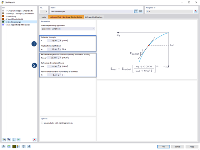
Rozszerzenie Analiza geotechniczna zapewnia programowi RFEM dodatkowe specyficzne modele materiałowe podłoża, które mogą odpowiednio odwzorować złożone zachowanie materiału podłoża. W tym artykule zaprezentujemy, w jaki sposób można określić zależną od naprężeń sztywność modeli materiałowych gruntu.

W tym artykule przedstawiono model połączenia zakładkowego płatwi ZL na dachu jednospadowym, obliczony w rozszerzeniu Połączenia stalowe i porównany z tabelą nośności podaną przez producenta.
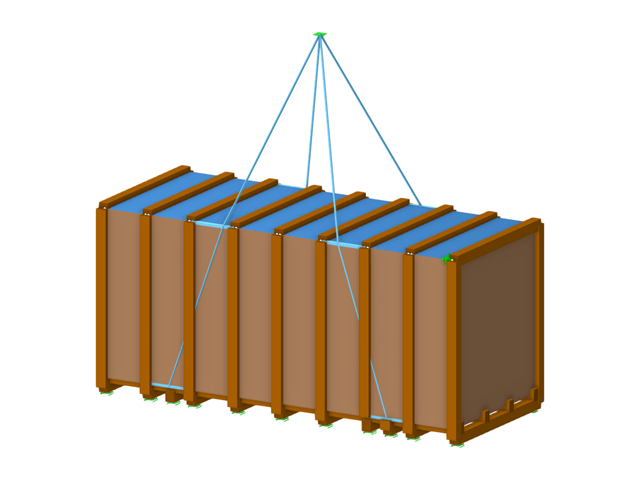
W tym artykule skrzynia na towary ciężkie jest obliczana zgodnie z wytycznymi Bundesverband Holzpackmittel (HPE). Obliczane są przypadki obciążeń dla obsługi dźwigiem i transportu morskiego.
Zgodność z przepisami budowlanymi, takimi jak Eurokod, jest niezbędna dla zapewnienia bezpieczeństwa, integralności konstrukcji i trwałości budynków i konstrukcji. Obliczeniowa mechanika płynów (CFD) odgrywa istotną rolę w tym procesie, symulując zachowanie płynów, optymalizując projekty i pomagając architektom i inżynierom w spełnieniu wymagań Eurokodu związanych z analizą obciążenia wiatrem, wentylacją naturalną, bezpieczeństwem pożarowym i efektywnością energetyczną. Integrując CFD z procesem projektowania, profesjonaliści mogą tworzyć bezpieczniejsze, wydajniejsze i zgodne z przepisami budynki, które spełniają najwyższe standardy konstrukcyjne i projektowe w Europie.
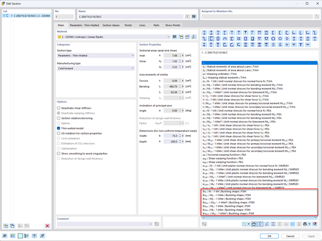
Aby umożliwić ocenę wpływu lokalnych zjawisk stateczności smukłych elementów, w programach RFEM 6 i RSTAB 9 można przeprowadzić liniową analizę obciążenia krytycznego na poziomie przekroju. Poniższy artykuł poświęcony jest podstawom obliczeń i interpretacji wyników.
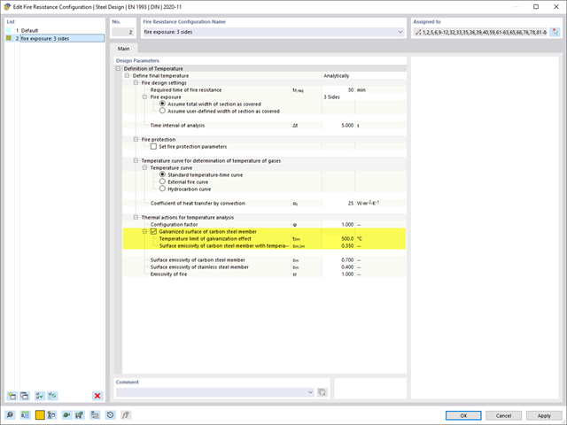
Rozszerzenie Projektowanie konstrukcji stalowych umożliwia wymiarowanie stalowych elementów konstrukcyjnych na wypadek pożaru, z zastosowaniem prostych metod obliczeniowych, zgodnie z Eurokodem 3. Temperatura elementu w chwili wykrycia może być określana automatycznie na podstawie krzywych temperatura-czas określonych w normie. Oprócz uwzględnienia okładzin przeciwpożarowych można również wziąć pod uwagę korzystne właściwości cynkowania ogniowego.
Program RFEM 6 oferuje rozszerzenie Wymiarowanie aluminium do wymiarowania prętów aluminiowych. W tym artykule pokazano, jak w programie obliczane są przekroje klasy 4 zgodnie z Eurokodem 9.
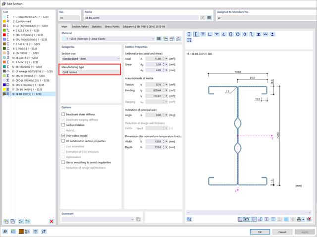
W tym artykule przedstawiono wymiarowanie przekrojów stalowych formowanych na zimno zgodnie z EN 1993-1-3, sekcja 6.1.6 w programie RFEM 6. Ponieważ temat jest nadal rozwijany, przedstawione zostaną aktualnie dostępne opcje.

Wymiarowanie prętów stalowych formowanych na zimno zgodnie z AISI S100-16 jest teraz dostępne w programie RFEM 6. Design can be accessed by selecting “AISC 360” as the standard in the Steel Design add-on. “AISI S100” is then automatically selected for the cold-formed design (Image 01).
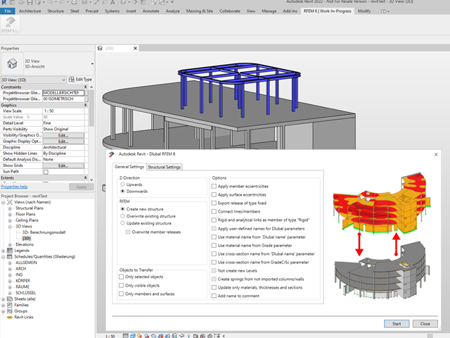
Podobnie jak w przypadku poprzednich generacji programów firmy Dlubal, zintegrowany interfejs z Autodesk Revit jest teraz dostępny dla programów RFEM 6 i RSTAB 9. W tym artykule przedstawiono ogólne informacje na temat interfejsu oraz obiektów konstrukcyjnych i parametrów związanych z firmą Dlubal w programie Revit.

Niniejszy artykuł jest związany z trwającym projektem, w ramach którego opracowywany i wdrażany jest cyfrowy bliźniak konstrukcyjny mostu Kalix w Szwecji.
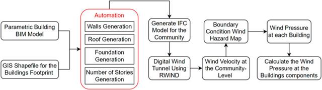
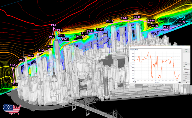
W artykule tym opracowano nowatorskie podejście do generowania modeli CFD na poziomie miejscowości poprzez połączenie modelowania informacji o budynku (BIM) i systemów informacji geograficznej (GIS) w celu zautomatyzowania generowania trójwymiarowego modelu terenu o wysokiej rozdzielczości, który zostanie wykorzystany jako dane wejściowe dla cyfrowego tunelu aerodynamicznego z wykorzystaniem RWIND.
Modelowanie ulicy wirowej Karmana w RWIND
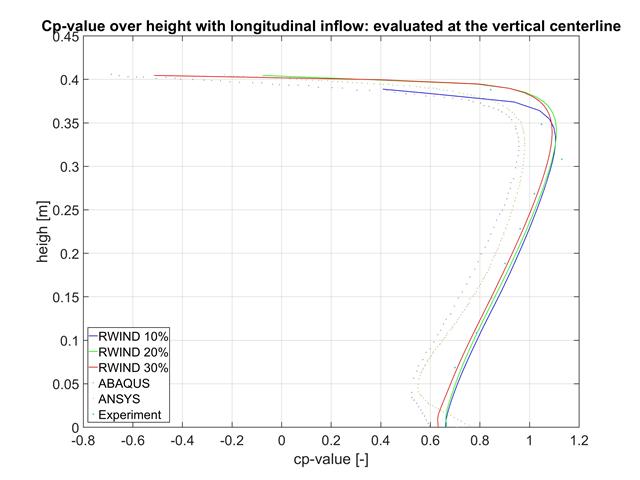
W tym artykule porównujemy wyniki z programów RWIND, ABAQUS i ANSYS z badaniem w tunelu aerodynamicznym przy użyciu prostego geometrycznie modelu.
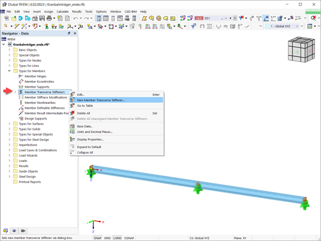
W tym artykule pokazano, jak definiować różne typy usztywnień poprzecznych pręta w programie RFEM 6 i RSTAB 9. Pokazano tu również, w jaki sposób uwzględnić je w projektowaniu i obliczeniach prętów o 7 stopniach swobody.

Jakość analizy statyczno-wytrzymałościowej budynków jest dużo lepsza, gdy można uwzględnić warunki gruntowe w sposób możliwie najbardziej realistyczny. W programie RFEM 6 można realistycznie określić kontur glebowy do analizy za pomocą rozszerzenia Analiza geotechniczna. Ten dodatek można aktywować w danych bazowych modelu, jak pokazano na rysunku 01.
Wraz z programami do analizy statyczno-wytrzymałościowej RFEM 6, RSTAB 9, RSECTION 1 i RWIND 2, Dlubal Software przedstawia nową generację programów do analizy statyczno-wytrzymałościowej. Getreu dem Motto „Statik, die Spaß macht…“ werden den Anwendern universelle Werkzeuge in die Hand gegeben, mit denen alle Anforderungen in der Tragwerksplanung bewältigt werden können. Was sich sonst noch bei Dlubal Software Neues getan hat, erfahren Sie in diesem Artikel.
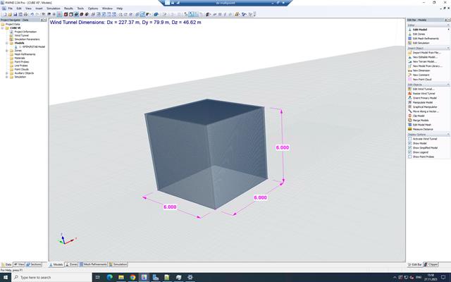
RWIND 2 to program do generowania obciążeń wiatrem w oparciu o CFD (Computational Fluid Dynamics). Symulacja numeryczna przepływu wiatru jest generowana wokół dowolnego budynku, w tym o nieregularnej lub niepowtarzalnej geometrii, w celu określenia obciążenia wiatrem powierzchni i prętów. RWIND 2 może być zintegrowany z programem RFEM/RSTAB w celu przeprowadzenia analizy statyczno-wytrzymałościowej lub jako samodzielna aplikacja.
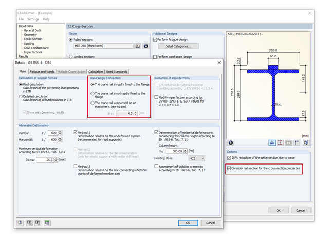
Die Wirkung der Schiene als "statisch mittragend" oder "statisch nicht mittragend" wird in KRANBAHN über die Auswahlmöglichkeiten "Schiene-Flanschverbindung" in den Details festgelegt. Diese Einstellung steuert die Berechnung der Lasteinleitungslänge nach EN 1993-6, Tab. 5.1.
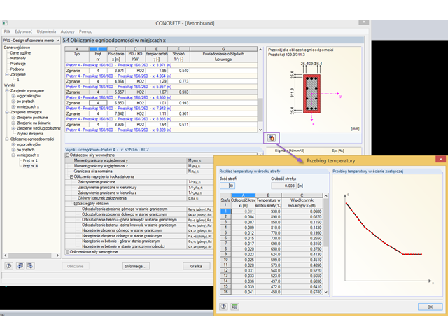
Wymiarowanie betonu zbrojonego na wypadek pożaru przeprowadza się zgodnie z metodą uproszczoną opartą na normie EN 1992-1-2, rozdz. 4.2. Dabei wird die im Anhang B.2 beschriebene "Zonenmethode" benutzt: Der Querschnitt wird in eine Anzahl paralleler Zonen gleicher Dicke unterteilt und deren temperaturabhängige Druckfestigkeit ermittelt. Die reduzierte Tragfähigkeit bei Brandeinwirkung wird so durch einen verkleinerten Bauteilquerschnitt mit abgeminderten Festigkeiten abgebildet.
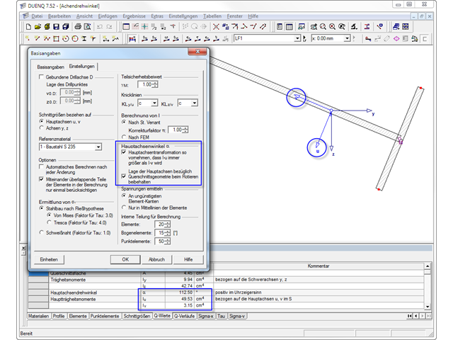
Allgemeine dünnwandige Querschnitte weisen oft unsymmetrische Geometrien auf. Die Hauptachsen solcher Profile liegen dann nicht parallel zu den horizontal und vertikal ausgerichteten Achsen Y und Z. Bei der Ermittlung der Querschnittswerte wird neben den hauptachsenbezogenen Trägheitsmomenten der Winkel α zwischen der Schwerpunktachse y und der Hauptachse u bestimmt.
Die Querschnittsprogramme DUENQ und DICKQ eignen sich, um die Querschnittskennwerte allgemeiner dünn- oder dickwandiger Profile zu ermitteln. Diese Querschnittswerte stehen auch für weitere Untersuchungen in RSTAB und RFEM zur Verfügung.
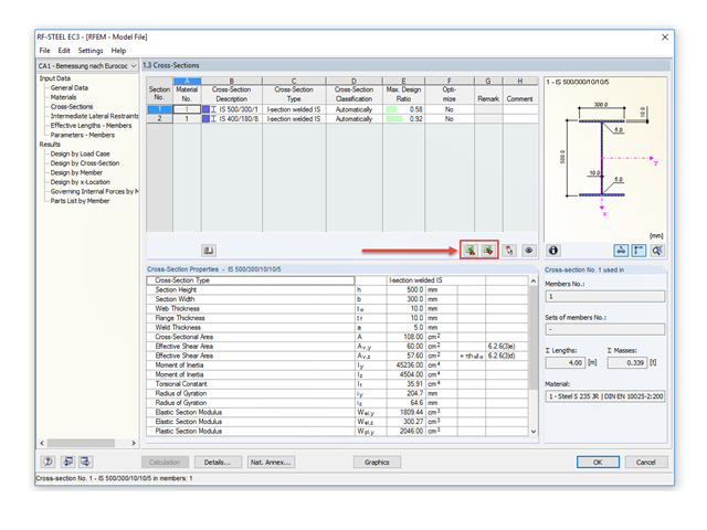
Mit RF-/STAHL EC3 ist es möglich, einen Querschnitt im Rahmen der Bemessung automatisch optimieren zu lassen. Dies erfolgt bei entsprechender Aktivierung in der Tabelle 1.3 auf Basis der aktuellen Profilreihe oder bei geschweißten Querschnitten im Rahmen der definierten variablen Parameter.
Konstrukcje różnie reagują na działanie wiatru, w zależności od sztywności, masy i tłumienia. Zasadniczo rozróżnia się budynki, które są podatne na drgania oraz takie, które nie są na nie podatne.
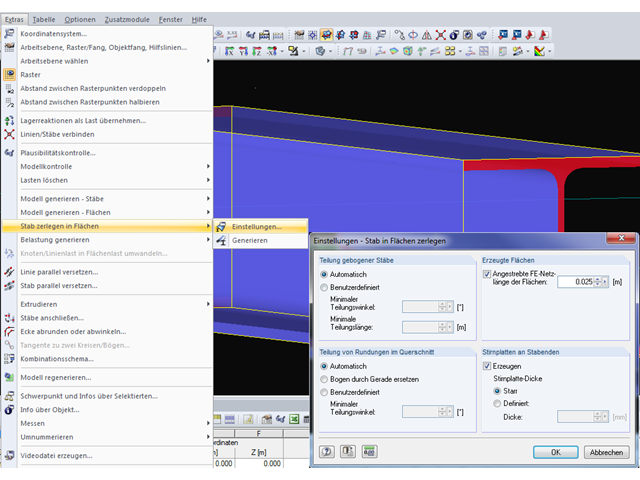
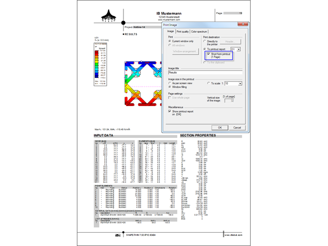
Program RFEM umożliwia automatyczne generowanie powierzchni z modelowanych prętów. Dies bietet den Vorteil, dass beispielsweise die Flächendicken eines Stahlprofils automatisch erzeugt werden.
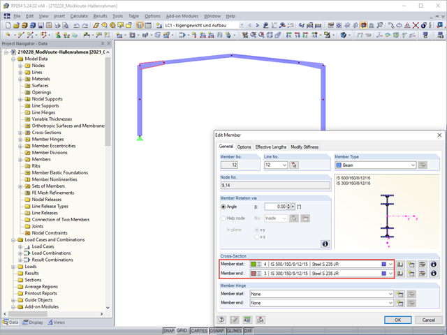
Vouten werden häufig mit coupierten Profilen ausgeführt. Bei der Modellierung sind jedoch einige Besonderheiten zu beachten, damit die Querschnitts- und Stabilitätsnachweise durchgeführt werden können.