58 Wyniki
Wyświetl wyniki:
Sortuj według:
- Wymiarowanie końców, prętów, podpór węzłowych, węzłów i powierzchni
- Uwzględnienie określonych obszarów obliczeniowych
- Kontrola wymiarów przekroju
- Wymiarowanie według EN 1995-1-1 (Europejska norma dotycząca drewna) zgodnie z odpowiednimi załącznikami krajowymi + DIN 1052 + DSTV DIN EN 1993-1-8 + ANSI/AWC - NDS 2015 (norma amerykańska)
- Projektowanie różnych materiałów, takich jak stal, beton i inne
- Nie ma konieczności łączenia się z konkretnymi normami
- Rozszerzalna biblioteka o elementy łaczące z drewna (SIHGA, Sherpa, WÜRTH, Simpson StrongTie, KNAPP, PITZL) i elementy stalowe (połączenia znormalizowane w konstrukcjach stalowych zgodnie z EC 3, M-connect, PFEIFER, TG-Technik)
- Nośności graniczne belek drewnianych firm STEICO i Metsä Wood dostępne w bibliotece
- Połączenie z MS Excel
- Optymalizacja elementów łączących (obliczany jest element najczęściej wykorzystywany)
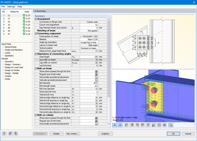
W kategorii Fundamenty przegubowe dostępne są cztery różne połączenia z blachą podstawy:
- Prosta podstawa słupa
- Zbieżna podstawa słupa
- Podstawa słupa dla prostokątnych profili zamkniętych
- Podstawa słupa dla okrągłych profili zamkniętych
W kategorii Podparcie dla słupów dostępnych jest pięć różnych układów połączeń dwuteowników:
- Podstawa słupa bez usztywnienia
- Podstawa słupa z żebrami usztywniającymi w środku pasa
- Podstawa słupa z żebrami usztywniającymi po obu stronach słupa
- Podstawa słupa z usztywnieniami ceowymi
- Fundament kielichowy
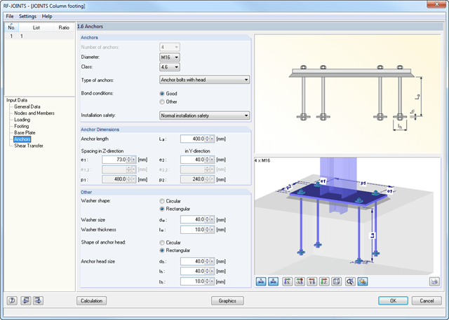
Wszystkie typy połączeń zawierają płytę podstawy przyspawaną do stalowego słupa. Połączenia za pomocą kotew są zabetonowane w fundamencie. Do wyboru są kotwy typu M12 - M42 o gatunkach stali 4.6 - 10.9. Górna i dolna strona kotew może być wyposażona w zaokrąglone lub kątowe blachy w celu lepszego rozłożenia obciążenia lub zakotwienia. Dodatkowo można zastosować prostokątne lub okrągłe głowice kotwiące z gwintem na końcach pręta.
Materiał i grubość warstwy zaprawy oraz wymiary i materiał podstawy można ustawić dowolnie. Ponadto można zdefiniować zbrojenie brzegowe stopy. Aby zapewnić lepsze przenoszenie sił tnących, na dolnej stronie blachy podstawy można zastosować skos (nakładka).
Siły tnące są przenoszone przez nakładki, kotwy lub tarcie. Poszczególne komponenty można łączyć.
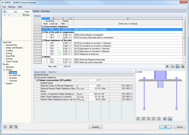
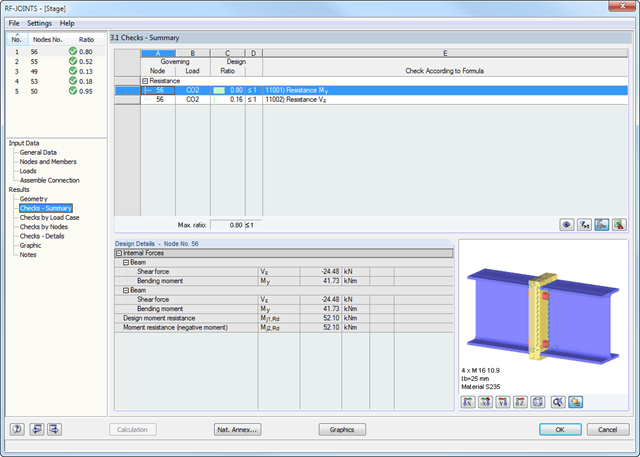
Po dokonaniu analizy moduł RF-/JOINTS Steel - Column Base pokazuje następujące obliczenia:
- Wymiarowanie przekroju netto
- Obliczenie docisku
- Siły tnące
- Nośność blokowa
- poślizg
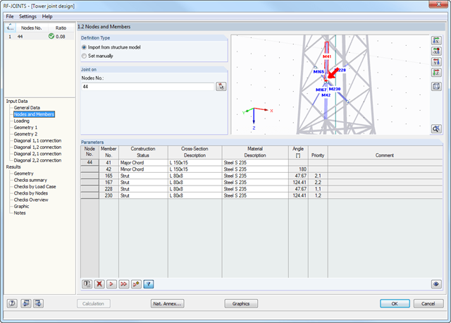
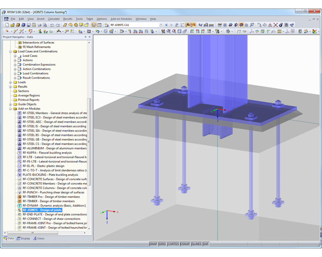
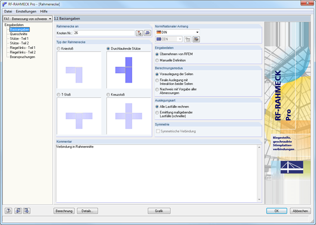
Po wybraniu w pierwszym oknie danych typu połączenia, kategorii połączenia oraz normy obliczeniowej, w oknie 1.2 można zdefiniować węzeł, który zostanie zaimportowany z programu RFEM/RSTAB i użyty do obliczeń połączenia. Opcjonalnie geometrię połączenia można zdefiniować ręcznie.
W kolejnych oknach wprowadzania można zdefiniować parametry połączenia, takie jak np. wprowadzenie obciążenia z programu RFEM/RSTAB lub, w przypadku ręcznego definiowania połączenia, obciążeń.
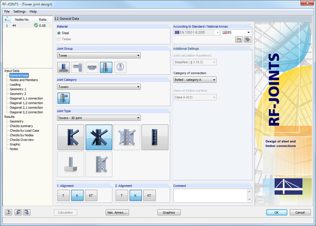
- Wybór różnych węzłów, np:
- Połączenia śrubowe krzyżulców bez blachy węzłowej 2D
- Połączenia śrubowe krzyżulców bez blachy węzłowej 3D
- Połączenia śrubowe słupów
- Połączenia typu T-, K- i KT z uwzględnieniem połączeń krzyżulców
- Różne kategorie połączenia do wyboru:
- A - zakładkowe/otworowe połączenia typu dociskowego
- B - połączenia cierne w stanie granicznym użytkowalności
- C - połączenia cierne w stanie granicznym nośności
- Śruby o klasach wytrzymałości od 4.6 do 10.9
- Średnice śrub od M12 do M42
- Możliwość modyfikacji rozstawów między śrubami
- Wizualizacja całego połączenia w oknie widoku
Główne funkcje wymiarowania połączeń są najpierw pogrupowane i wyświetlane wraz z podstawową geometrią połączenia w pierwszym oknie wyników. W pozostałych tabelach wyników można zobaczyć wszystkie istotne szczegóły obliczeń, takie jak nośność kotew, naprężenia w spoinach itp.
Wymiary, specyfikacje materiałowe i spoiny, które są istotne dla konstrukcji połączenia, są widoczne od razu i można je wydrukować. Połączenia można zwizualizować w module dodatkowym RF-/JOINTS Steel - Column Base lub w modelu RFEM/RSTAB.
Wszystkie grafiki mogą zostać dołączone do protokołu wydruku programu RFEM/RSTAB lub wydrukowane bezpośrednio. Dzięki skalowaniu wyników, możliwa jest optymalna kontrola wizualna już na etapie projektowania.
Po dokonaniu analizy moduł RF-/JOINTS Steel - Column Base pokazuje następujące obliczenia:
- Wytrzymałości na zginanie podstawy słupa
- Rozciągania kotew oraz siły ścinające w kotwach
- Wytrzymałości na scinanie klina
- Ściskania betonu / zniszczenia krawędzi betonu
- Tarcie
- Spoiny
Po wybraniu w pierwszym oknie wprowadzania typu zakotwienia i normy obliczeniowej, w oknie 1.2 należy zdefiniować węzeł, który ma zostać zaimportowany z programu RFEM/RSTAB i w którym ma zostać przeprowadzone wymiarowanie zakotwienia.
Opcjonalnie można ręcznie zdefiniować przekrój i materiał słupa. W kolejnych oknach wprowadzania można zdefiniować parametry punktu bazowego, takie jak np. Obciążenie jest importowane z programu RFEM/RSTAB lub, w przypadku ręcznej definicji połączenia, wprowadzone obciążenia.
Uwzględniane są wszystkie typy połączeń z momentem na pasie słupa lub na środniku słupa w przypadku słupa obróconego. Z tego względu moduł określa moment mimośrodowy połączenia nakładek na środniku z blachą środnika, który dodatkowo wpływa na grupę śrub w pasie dźwigara.
Kolejne momenty mimośrodowe mogą wynikać z położenia kątowników i blach. W przypadku połączenia nakładkowego siły są przenoszone osobno. Na nakładkę działają siły tnące; siły rozciągające i moment stabilizujący są przypisane do śrub. Przed obliczeniami połączenie jest sprawdzane pod kątem poprawności geometrycznej; na przykład rozstaw otworów na śruby i odległość śrub od krawędzi.
Wyniki zawierają szczegółowe informacje na temat analizowanych sił wewnętrznych, kryteriów obliczeniowych oraz granic. Niezadowalające wyniki obliczeń są jasno zaznaczone.
Wszystkie dane początkowe i wyniki są również udokumentowane w ogólnym protokole wydruku programu RFEM/RSTAB. Oddzielne przypadki obliczeniowe pozwalają na elastyczne badanie poszczególnych części dużych konstrukcji.
Pomyślne sprawdzenie obliczeń opiera się na sprawdzeniu poprawności warunków geometrycznych.
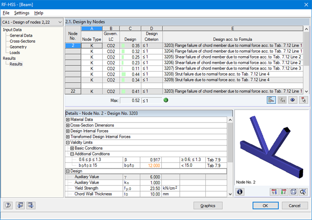
RF-/HSS prowadzi analizę dla następujących typów obliczeń:
- Uszkodzenie półki w belce pasa spowodowane siłą normalną
- Uszkodzenie przez ścięcie prętów pasa spowodowane siłą normalną
- Uszkodzenie zastrzału spowodowane siłą normalną
- Przebicie spowodowane siłą normalną
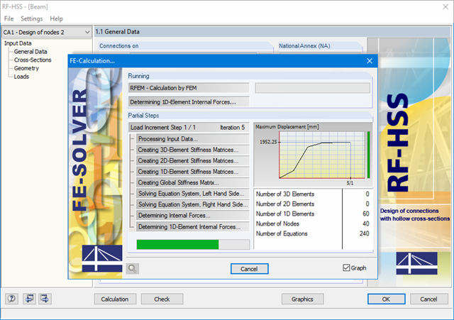
- Integracja z RFEM/RSTAB z automatycznym rozpoznawaniem geometrii i przenoszeniem sił wewnętrznych
- Możliwość ręcznego definiowania połączeń
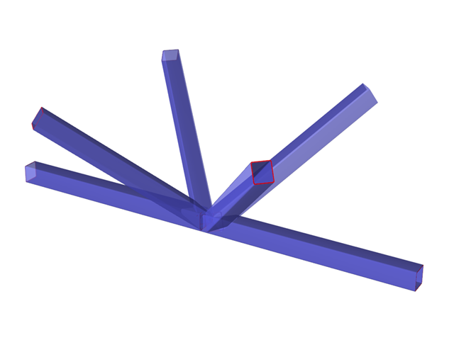
- Obszerna biblioteka przekrojów rurowych dla pasów i stężeń:
- przekroje okrągłe
- przekroje kwadratowe
- przekroje prostokątne
- Dostępne klasy stali: S 235, S 275, S 355, S 420, S 450 oraz S 460
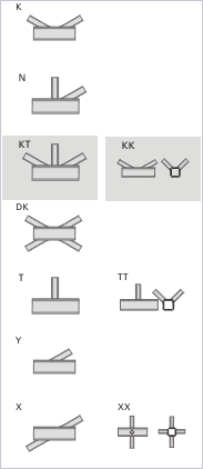
- W zależności od specyfikacji standardowej dostępne są różne typy połączeń:
- Połączenie K (przerwa/przekrycie)
- Połączenie KK (przestrzenne)
- Połączenie N (przerwa/przekrycie)
- Połączenie KT (przerwa/przekrycie)
- Połączenie DK (przerwa/przekrycie)
- Połączenie T (płaszczyznowe)
- Połączenie TT (przestrzenne)
- Połączenie Y (płaszczyznowe)
- Połączenie X (płaszczyznowe)
- Połączenie XX (przestrzenne)
- Wybór częściowych współczynników bezpieczeństwa zgodnie z załącznikiem krajowym dla Niemiec, Austrii, Czech, Słowacji, Polski, Słowenii, Szwajcarii i Danii
- Dostosowywanie kątów pomiędzy pasami i stężeniami
- Opcjonalny obrót pasów o 90° dla prostokątnych przekrojów rurowych
- Możliwość uwzględniania przerw pomiędzy stężeniami lub ich wzajemnego pokrywania się
- Opcjonalne uwzględnianie dodatkowych sił węzłowych
- Obliczanie połączenia jako maksymalna nośność krzyżulców kratownicy dla sił osiowych i momentów zginających
Po pierwsze, moduł łączy w sobie decydujące obliczenia dla słupa i belki poziomej oraz wyświetla geometrię połączenia w tabeli wyników. Inne tabele wyników zawierają wszystkie ważne szczegóły obliczeń, takie jak długości linii płynięcia, nośność śrub, naprężenia w spoinach lub sztywności połączeń. Wszystkie połączenia przedstawiane są w graficznym renderowaniu 3D.
Wymiary, specyfikacje materiałowe i spoiny, które są istotne dla konstrukcji połączenia, są widoczne od razu i można je wydrukować. Połączenia można przedstawić graficznie w dodatkowym module RF-/FRAME-JOINT Pro lub bezpośrednio w modelu programu RFEM/RSTAB. Wszystkie grafiki mogą zostać dołączone do protokołu wydruku programu RFEM/RSTAB lub wydrukowane bezpośrednio. Dzięki skalowaniu wyników, możliwa jest optymalna kontrola wizualna już na etapie projektowania.
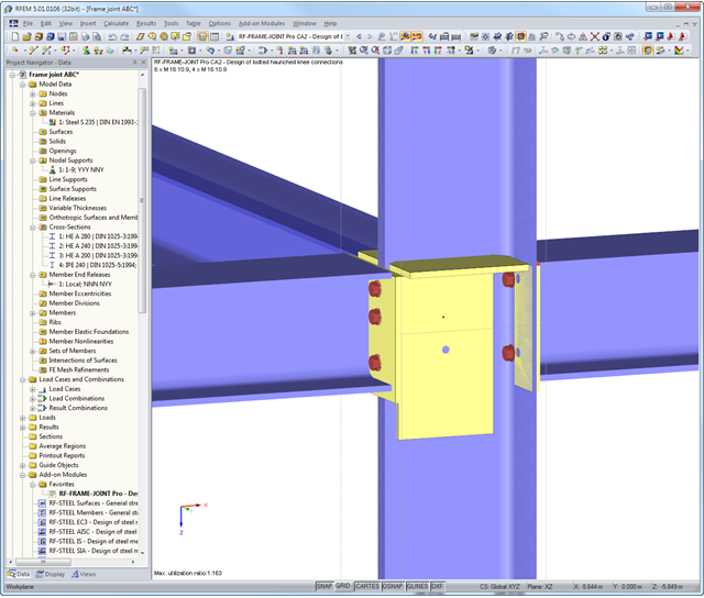
RF-/FRAME-JOINT Pro przeprowadza następujące obliczenia według EN 1993-1-8 lub DIN 18800:
- Płyta czołowa belki i półka słupa według teorii przegubu plastycznego
- Sworznie dla rozciągania (wraz z siłami kontaktowymi)
- Sworznie dla ścinania
- Wprowadzanie siły rozciągającej w środniku słupa i środniku belki
- Obliczanie wyboczenia dla płyty wachlarzowej
- Obliczanie ścinania dla płyty wachlarzowej
- Wprowadzanie siły ściskającej w środniku słupa oraz obliczanie wyboczenia dla płyty środnika
- W razie potrzeby:
- Obliczanie usztywnienia poprzecznego
- usztywnienie w środniku
- Wzmocnienie środnika dodatkową blachą
- Wprowadzanie siły ściskającej w belce poziomej
- Projektowanie spoin
Węzły połączenia można wybierać graficznie w modelu programu RFEM/RSTAB. Odpowiednie dane przekroju i geometria są importowane automatycznie. Parametry połączeń profili rurowych można również zdefiniować ręcznie. W razie potrzeby przekroje można modyfikować w module.
Domyślny kąt między krzyżulcami a pasami można również zmienić. Geometryczny stosunek krzyżulców do siebie jest ważny dla prawidłowego wyboru obliczeń. Zależność tę można zdefiniować poprzez określenie odstępu między zastrzałami lub poprzez ich zachodzenie na siebie.
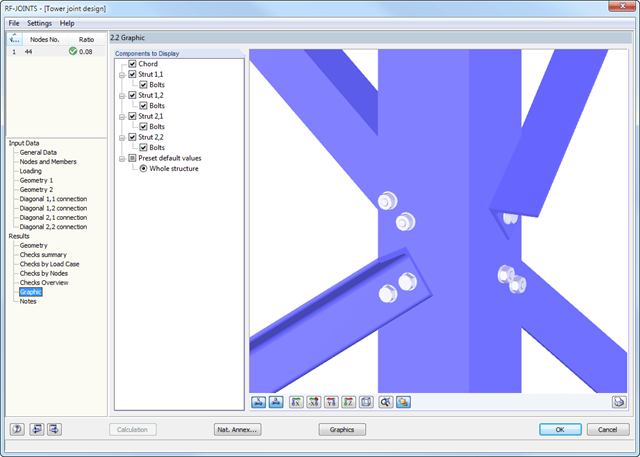
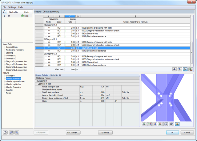
Główne funkcje wymiarowania połączeń są najpierw pogrupowane i wyświetlane wraz z podstawową geometrią połączenia w pierwszym oknie wyników. W innych tabelach wyników można zobaczyć wszystkie podstawowe szczegóły obliczeń, takie jak nośność na docisk, ścinanie, poślizg i inne.
Wymiary, właściwości materiału i spoiny istotne dla konstrukcji połączenia są wyświetlane natychmiast i można je wydrukować. Połączenie może zostać przedstawione graficznie w module dodatkowym RF-/JOINTS Steel - Tower lub bezpośrednio w modelu programu RFEM/RSTAB.
Wszystkie grafiki mogą zostać dołączone do protokołu wydruku programu RFEM/RSTAB lub wydrukowane bezpośrednio. Dzięki skalowaniu wyników, możliwa jest optymalna kontrola wizualna już na etapie projektowania.
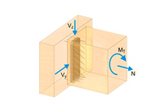
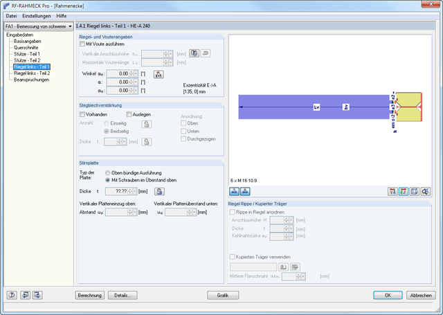
- Projektowanie połączeń kolanowych, teowych, krzyżowych i ciągłych połączeń słupów o przekrojach dwuteowych
- Import geometrii i danych obciążenia z programu RFEM/RSTAB lub ręczna specyfikacja połączenia (np. do ponownego obliczenia bez istniejącego modelu w RFEM/RSTAB)
- Połączenia zlicowane z górą lub połączenia z rzędem śrub w przedłużeniu
- Obliczanie dodatnich i ujemnych momentów w połączeniach ramy
- Różne kąty nachylenia prawych i lewych belek poziomych oraz zastosowanie w ramach dachów dwuspadowych i jednospadowych
- Uwzględnienie dodatkowych pasów w belce poziomej, na przykład w przypadku przekrojów o zbieżnym przekroju
- Symetryczne i asymetryczne połączenia teowe lub krzyżowe
- Dwustronne połączenie z różnymi wysokościami przekroju po prawej i lewej stronie
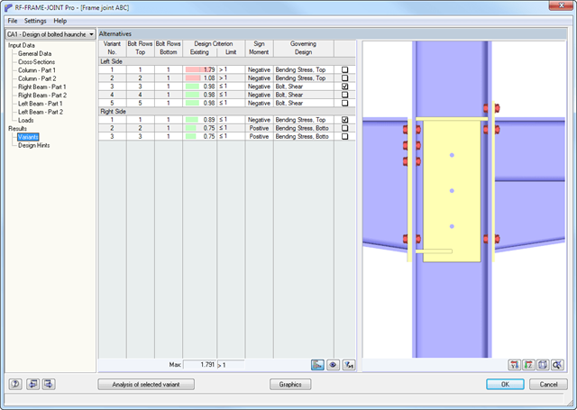
- Automatyczny wstępny projekt rozmieszczenia śrub i wymaganego usztywnienia
- Opcjonalny tryb obliczeń z możliwością definiowania wszystkich rozstawów śrub, spoin i grubości blachy
- Sprawdzenie zdolności do skręcania śrub z możliwością dostosowania wymiarów zastosowanych kluczy
- Klasyfikacja połączeń za pomocą sztywności i obliczanie sztywności sprężystej połączeń uwzględnianych przy określaniu sił wewnętrznych
- Sprawdź do 45 pojedynczych obliczeń (elementów) połączenia
- Automatyczne określanie decydujących sił wewnętrznych dla każdego obliczenia z osobna
- Możliwość wyświetlania grafiki połączeń w trybie renderowania ze specyfikacjami dotyczącymi materiału, grubości blachy, spoin, rozstawu śrub i wszystkich wymiarów konstrukcyjnych
- Zintegrowane i elastycznie rozszerzalne ustawienia załączników krajowych zgodnie z normą EN 1993-1-8
- Automatyczna konwersja sił wewnętrznych z analizy statyczno-wytrzymałościowej na odpowiednie przekroje, również w przypadku mimośrodowych połączeń prętów
- Automatyczne określanie sztywności początkowej Sj,ini połączenia
- Szczegółowa kontrola poprawności wszystkich wymiarów, wraz z podaniem wprowadzanych wartości granicznych (np. dla odległości od krawędzi i rozstawu otworów)
- Możliwość przyłożenia sił ściskających do słupa poprzez kontakt
- Możliwość aktualizacji wysokości przekroju belek poziomych w przypadku połączeń o zmiennym przekroju po zoptymalizowaniu geometrii połączenia w RF-/FRAME-JOINT Pro
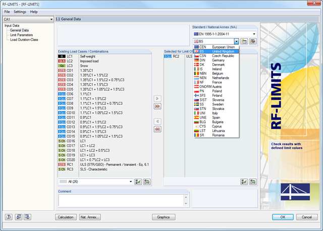
Po wybraniu obciążeń wymaganych do obliczeń oraz, w razie potrzeby, żądanej normy do obliczeń, w oknie 1.2 Parametry graniczne można zdefiniować obciążenia graniczne. Możliwe jest dodawanie innych producentów do listy w bazie danych.
Po wybraniu wszystkich elementów granicznych do obliczeń można opcjonalnie zdefiniować klasę trwania obciążenia (KTO). Trzecie okno modułu jest dostępne jedynie w przypadku wymiarowania elementów połączeń drewnianych wg EN 1995-1-1 lub DIN 1052.
Moduł dodatkowy RF-/FRAME-JOINT Pro służy do wymiarowania połączeń konstrukcji, obliczonych w programie RFEM/RSTAB. Jeżeli konstrukcja w programie RFEM/RSTAB nie jest dostępna, geometrię i obciążenie można zdefiniować ręcznie; na przykład podczas sprawdzania obliczeń zewnętrznych.
W programie RFEM/RSTAB wybiera się węzeł do obliczenia. Moduł automatycznie rozpoznaje wszystkie połączone pręty i przydziela im typ połączenia. W zależności od typu połączenia, można zdefiniować dalsze szczegóły żeber, blach oporowych, blach środnika, śrub, spoin oraz rozstawu otworów. Jako obciążenia można wybrać dowolny przypadek obciążenia, kombinację obciążeń lub kombinację wyników w programie RFEM/RSTAB.
W przypadku pracy w trybie "obliczeń wstępnych", RF-/FRAME-JOINT Pro przeprowadza pierwszy krok obliczeń, aby zasugerować odpowiednie ułożenia. Po wybraniu odpowiedniego układu moduł wyświetla wszystkie obliczenia w szczegółowych tabelach wyników i grafice.
.png?mw=640&hash=c9c52de2eed98a2905a02fbf54b073f645c0df2c)
- Obliczanie połączeń przenoszących moment oraz przegubowych dla walcowanych przekrojów w kształcie litery I, według Eurokodu 3:
- Połączenia z blachą czołową przenoszącą moment (typ IH/IM)
- Połączenia przegubowe spawane (typ PM)
- Połączenia proste z kątownikami normalnymi lub nierównoramiennymi (typ IW lub IG)
- Proste połączenia przy użyciu blach czołowych zamontowanych tylko na środniku bądź na środniku i pasach (typ IS)
- Możliwość łączenia połączeń w wycięciem (IK) z przegubowymi płytami czołowymi (IS) oraz z połączeniami łącznikiem środnikowym (IW)
- Automatyczne rozmieszczenie śrub dla danego połączenia (dla wszystkich typów)
- Sprawdzanie wymaganej grubości pręta przenoszącego obciążenie w połączeniach ścinanych
- Podawanie wszystkich wymaganych szczegółów konstrukcyjnych, takich jak urządzenia, układ otworów, potrzebnych wysięgników, ilość śrub, wymiary płyty czołowej oraz spoin
- Podawanie sztywności S j,ini dla połączeń przenoszących zginanie
- Dokumentacja dostępnych obciążeń i porównywanie ich z nośnościami
- Podawanie stopnia wykorzystania dla każdego pojedynczego połączenia
- Automatyczne określanie głównych sił wewnętrznych dla kilku przypadków obciążeń oraz węzłów połączeniowych
Po zakończeniu obliczeń wszystkie wyniki są wyświetlane w przejrzyście ułożonych tabelach wyników; na przykład według przypadku obciążenia lub według węzła. Decydujące siły wewnętrzne są porównywane z wartościami granicznymi wymienionymi w wytycznych DSTV.
Połączenia można zwizualizować graficznie w module dodatkowym lub w programie RFEM/RSTAB. Oprócz danych wejściowych i wyników, w tym szczegółowych informacji dotyczących obliczeń, wyświetlanych w tabelach, do protokołu wydruku można dodać wszystkie grafiki. W ten sposób dokumentacja jest przejrzysta i zrozumiała.
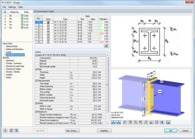
Obszerne wytyczne DSTV znajdują się w specjalnej bazie danych zintegrowanej w module DSTV. Każde połączenie jest opisane niepowtarzalnym kodem alfanumerycznym.
Możliwe połączenia DSTV można odfiltrować na podstawie odpowiednich ustawień dla typu połączenia DSTV (IH, IW, IS, IG oraz IK) oraz zastosowanego przekroju. W ten sposób można określić nośność wybranego połączenia.
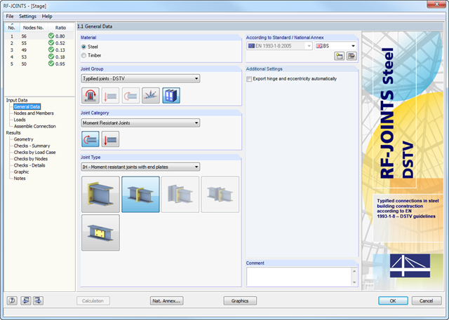
Po otwarciu modułu dodatkowego należy wybrać typ połączenia (przegubowe lub przegubowe połączenie z belką dwuteową). Poszczególne węzły można wybrać graficznie w modelu programu RFEM/RSTAB.
Moduł dodatkowy RF-/JOINTS Steel - DSTV automatycznie rozpoznaje przekrój wraz z odpowiednim materiałem i sprawdza, czy możliwe jest wymiarowanie połączenia zgodnie z wytycznymi DSTV. Ponadto można modelować i wymiarować połączenia o podobnej konstrukcji w kilku miejscach konstrukcji belki.
Wyniki analizy skręcania skrępowanego są wyświetlane w modułach RF-/STEEL AISC i RF-/STEEL EC3 w zwykły sposób. Odpowiednie okna wyników zawierają między innymi wartości krytycznego skręcania i skręcania, siły wewnętrzne oraz podsumowanie obliczeń.
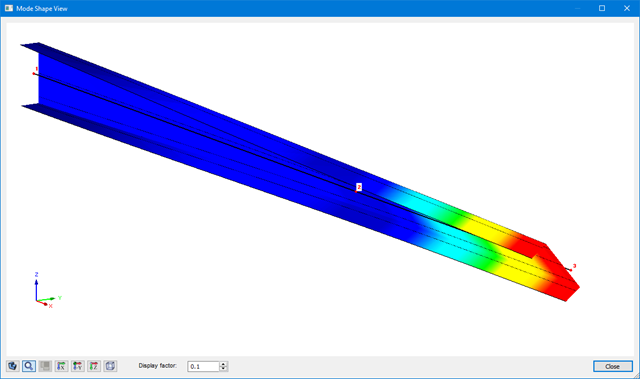
Graficzne przedstawienie postaci drgań (wraz z deplanacją) umożliwia realistyczną ocenę zachowania się wyboczenia.
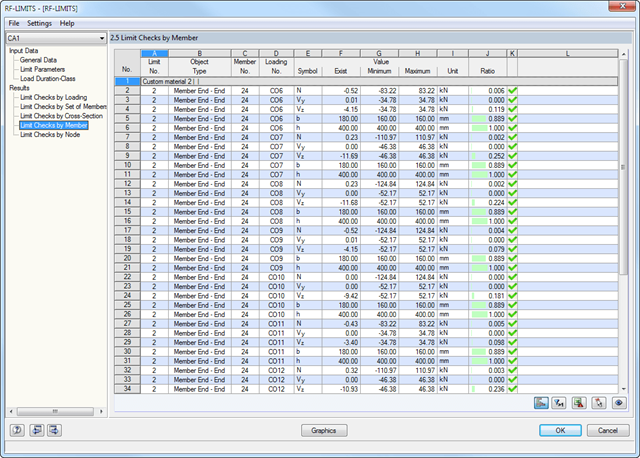
Najpierw wyświetlane są decydujące obliczenia połączenia dla danego przypadku obciążenia oraz kombinacji obciążeń lub kombinacji wyników. Ponadto możliwe jest oddzielne wyświetlanie wyników dla zbiorów prętów, przekrojów, prętów, węzłów i podpór węzłowych.
- Możesz użyć filtra, aby jeszcze bardziej zredukować wyświetlane wyniki, a tym samym przedstawić je w bardziej przejrzysty sposób.
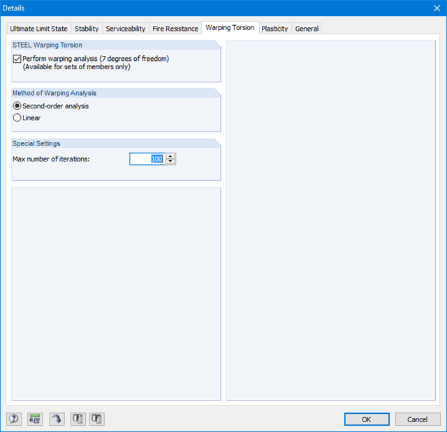
Ponieważ moduł RF-/STEEL Warping Torsion jest w pełni zintegrowany z modułami RF-/STEEL AISC i RF‑/STEEL EC3, dane są wprowadzane w taki sam sposób, jak w przypadku obliczeń w tych modułach. W oknie dialogowym Szczegóły, zakładka Skręcanie skrępowane (patrz rysunek po prawej stronie), konieczne jest tylko zaznaczenie opcji "Przeprowadzić analizę skręcania skrępowanego". W tym oknie dialogowym można również zdefiniować maksymalną liczbę iteracji.
Analiza skręcania skrępowanego jest przeprowadzana dla zbiorów prętów w modułach RF-/STEEL AISC i RF-/STEEL EC3. Można dla nich zdefiniować warunki brzegowe, takie jak podpory węzłowe lub zwolnienia na końcach prętów.
Możliwe jest również określenie imperfekcji do obliczeń nieliniowych.
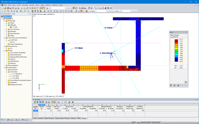
SHAPE-THIN określa wszystkie odpowiednie charakterystyki przekroju, wraz z plastycznymi siłami granicznymi i momentami. Nakładające się powierzchnie są uwzględniane w sposób realistyczny. Dla przekrojów utworzonych z różnych materiałów, SHAPE-THIN określa idealne charakterystyki przekroju w odniesieniu do materiału referencyjnego.
Oprócz analizy naprężeń w stanie sprężystym, można prowadzić również obliczenia w stanie plastycznym, zawierające interakcję sił wewnętrznych dla różnorodnych kształtów przekroju. Obliczenia interakcji plastycznej prowadzane są według metody Simplex. Podczas analizy naprężeń można wybrać różne teorie (Tresca lub von Mises).
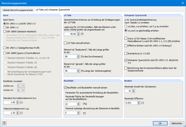
SHAPE-THIN przeprowadza klasyfikację przekroju zgodnie z EN 1993-1-1 i EN 1999-1-1. W przypadku przekrojów stalowych o przekroju 4, program określa szerokości efektywne dla płyt usztywnionych lub nieusztywnionych, zgodnie z EN 1993-1-1 i EN 1993-1-5. W przypadku przekrojów aluminiowych o przekroju klasy 4, program oblicza grubości efektywne zgodnie z EN 1999-1-1.
Opcjonalnie SHAPE-THIN sprawdza wartości graniczne c/t zgodnie z metodami obliczeniowymi el-el, el-pl lub pl-pl zgodnie z DIN 18800. Przekrój jest klasyfikowany według danej kombinacji sił wewnętrznych.
SHAPE-THIN posiada obszerną bibliotekę przekrojów walcowanych i parametryzowanych. Mogą one być łączone lub uzupełniane o nowe elementy. Możliwe jest zamodelowanie przekroju składającego się z różnych materiałów.
Narzędzia i funkcje graficzne umożliwiają modelowanie złożonych kształtów przekrojów w sposób typowy dla programów CAD. W oknie graficznym można wprowadzić elementy punktowe, spoiny pachwinowe, łuki, sparametryzowane przekroje prostokątne i okrągłe, elipsy, łuki eliptyczne, parabole, hiperbole, splajn oraz NURBS. Alternatywnie można zaimportować plik DXF, który stanowi podstawę do dalszego modelowania. Podczas modelowania można użyć także linii pomocniczych.
Ponadto, sparametryzowane wprowadzanie danych umożliwia wprowadzanie danych modelu i obciążeń w określony sposób, tak aby były one zależne od określonych zmiennych.
Elementy można graficznie podzielić lub przydzielić do innych obiektów. SHAPE-THIN automatycznie dzieli elementy i zapewnia nieprzerwany przepływ ścinający poprzez wprowadzenie elementów zerowych. W przypadku elementów zerowych można zdefiniować określoną grubość, aby kontrolować przenoszenie ścinania.
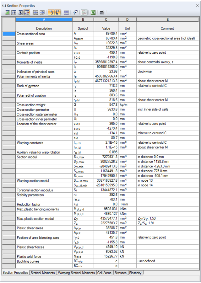
SHAPE-THIN określa charakterystyki przekroju i naprężenia dla przekrojów otwartych, zamkniętych, połączonych i niepołączonych.
- parametry przekroju
- Pole przekroju A
- Pole ścinane Ay, Az, Au i Av
- Położenie środka ciężkości yS, zS
- momenty pola 2 stopnie Iy, Iz, Iyz, Iu, Iv, Ip, Ip,M
- Promienie bezwładności iy, iz, iyz, iu, iv, ip, ip,M
- Nachylenie osi głównych α
- Ciężar przekroju G
- Średnica przekroju U
- momenty bezwładności przy skręcaniu stopnieIT , IT , IT,St.Venant, IT,Bredt, IT,s
- Położenie środka ścinania yM, zM
- Stałe deplanacji Iω,S, Iω,M or Iω,D dla utwierdzenia bocznego
- Max/min moduły przekroju Sy, Sz, Su, Sv, Sω,M z położeniami
- Promienie przekroju ru, rv, rM,u, rM,v
- Współczynnik redukcyjny λM
- Plastyczne charakterystyki przekroju
- Siła osiowa Npl,d
- Siły tnące Vpl,y,d, Vpl,z,d, Vpl,u,d, Vpl,v,d
- Momenty zginające Mpl,y,d, Mpl,z,d, Mpl,u,d, Mpl,v,d
- Moduły przekroju Zy, Zz, Zu, Zv
- Pola ścinania Apl,y, Apl,z, Apl,u, Apl,v
- Położenie osi powierzchni fu, fv,
- Wyświetlanie elipsy bezwładności
- Momenty statyczne pola Qu, Qv, Qy, Qz z położeniem maksimum i określeniem przebiegu ścinania
- Współrzędne wycinkowe ωM
- momenty bezwładności (wycinkowe powierzchnie) Sω,M
- Pola komórek Am zamkniętych przekrojów
- Naprężenia normalne σx wywołane siłą osiową, momentem zginającym i bimomentem deplanacji
- Naprężenia styczne τ od sił tnących oraz pierwotnych i drugorzędnych momentów skręcających
- Naprężenia zastępcze σv ze współczynnikiem dla naprężeń ścinających, który można dostosować do własnych potrzeb
- Stopnie wykorzystania odniesione do naprężeń granicznych
- Naprężenia dla krawędzi lub osi elementu
- Naprężenia w spoinach pachwinowych
- Charakterystyki przekrojów niepołączonych (rdzeń budynku wysokościowego, przekroje złożone)
- Siły tnące wywołane zginaniem i skręcaniem
- Obliczanie nośności plastycznej z określeniem współczynnika zwiększającego αpl
- Sprawdzenie stosunków c/t według metody el-el, el-pl lub pl-pl wg DIN 18800