For stability analysis according to the equivalent member method, it is necessary to define effective or lateral-torsional buckling lengths in order to determine a critical load for the stability failure.
After assigning an effective length to an object to be designed, the corresponding settings and the effective lengths for this object are considered in the stability analysis. If no effective length is defined, but the stability analysis is activated, a warning is displayed as a result (see also the result table Errorsnbsp;& Warnings).
Main
In the "Main" tab, you can make basic specifications. The effective length factors are entered and the nodal supports to be considered are defined in the Nodal Supports & Effective Lengths tab. The input options are adjusted according to the selected design standard. Therefore, not all options are always available. The design standard is selected in the Base Data of the model (see also Chapter Standards I of the RFEM manual).
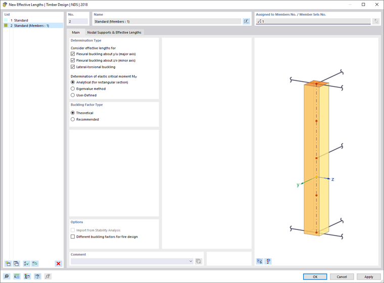
Determination Type
Use the check boxes to specify which forms of stability failure are to be checked for the member or member set. Under compression, flexural buckling about the major or minor axis can become governing. The "Lateral-torsional buckling" option activates the design for lateral-torsional buckling under bending. Depending on the selected design standard, there are various options for calculating the critical lateral-torsional buckling moment Mcr or the critical bending stress.
Buckling Factor Type
American design standards differentiate between the theoretical and the recommended values of the effective length factors. The effective length factors that can be defined as a template for the members restrained on one side, for example, are adjusted according to the selection.
Options
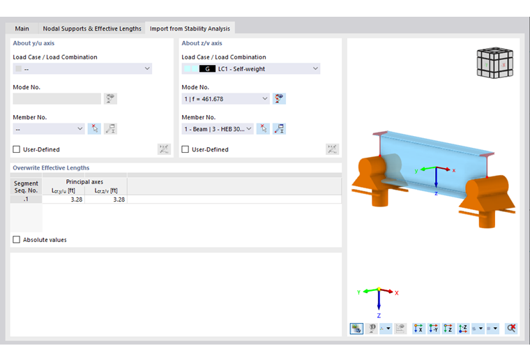
The "Import from Stability Analysis" check box allows you to apply the effective length factors based on buckling modes. The corresponding entries can be specified in the additional tab "Import from Stability Analysis" (see the image Importing Effective Lengths). This option is available if the Structural Stability Analysis add-on has been activated.
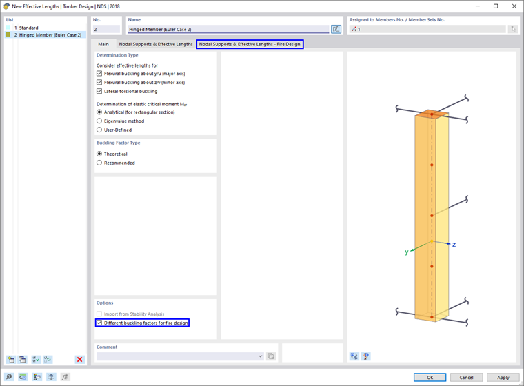
If you select the "Different buckling factors for fire design" option, another tab "Nodal Supports & Effective Lengths – Fire Design" appears. Here you can define different effective lengths for the fire resistance design than for the design at normal temperature. The entry is the same as for the cold-state design and is explained below.
Nodal Supports & Effective Lengths
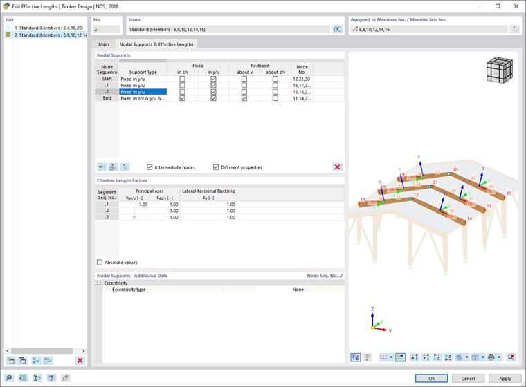
Nodal Supports
By entering nodal supports, you define the boundary conditions for the lateral-torsional buckling analysis (for the "Eigenvalue Method" determination type only). Furthermore, the nodal supports are used to subdivide the member or the member set into segments.
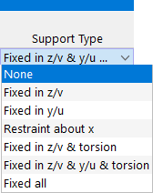
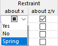
To define the supports, you can select common types from the list in the left column, activate the check boxes in the cells individually (fixed supports), or deactivate them (no supports).
In addition to fixed or rigid supports, you can also define spring parameters for the relevant directions. For this, use the cell shortcut menu. You can enter a spring stiffness in the Nodal Supports section.
You can define the support conditions at the start, at the end, and at intermediate nodes. Standard nodes between the members of a member set and "nodes on members" are considered as intermediate nodes (see Chapter Nodes of the RFEM manual).
The definition of intermediate nodes is not based on node numbers, but on the order on the member: .1 designates the first intermediate node from the member start, .2 the second one, and so on. If a member with this effective length has more or less intermediate nodes, the consideration based on the member start applies and the excess entries or nodes are ignored.
Using the
![]() button, you can insert a new intermediate node above the selected line. To delete an intermediate node, select the line and click the button
button, you can insert a new intermediate node above the selected line. To delete an intermediate node, select the line and click the button
![]() . The table shortcut menu also provides the options for editing rows.
. The table shortcut menu also provides the options for editing rows.
Use the
![]() button on the left to select a member or a member set in the model, and to automatically transfer the number of intermediate nodes on this member set to the table. If the effective length is already assigned to a member or a member set, you can select a node by clicking the
button on the left to select a member or a member set in the model, and to automatically transfer the number of intermediate nodes on this member set to the table. If the effective length is already assigned to a member or a member set, you can select a node by clicking the
![]() button on the right. In the table with nodal supports, the row of the associated intermediate support is selected automatically (if available).
button on the right. In the table with nodal supports, the row of the associated intermediate support is selected automatically (if available).
Once you have assigned the effective length to a member or member set, you can check the supports using theimage
Supports at the intermediate nodes subdivide the member or member set into several segments for various failure cases: The designation of the factors can vary, depending on the selected design standard.
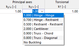
An arrow symbolizes an effective length factor across segments, if there is no corresponding intermediate support in the "Nodal Support" table. You can define the effective length factors of the individual segments in the table rows, and thus adapt the effective lengths of the sections. For common cases, you can use the predefined values from the cell shortcut menu.
The effective length used for the design of a failure mode at a location in this segment results from the multiplication of the segment length by the corresponding effective length factor.
You can also specify absolute values for the effective lengths. Please note that these values are used for all assigned objects. In contrast to the use of the effective length factors, there is no relative adjustment to the actual segment length. Therefore, you should prefer the definition via the effective length factors to the entry of absolute values for the effective length.
For the lateral-torsional buckling design with the eigenvalue solver, the total length of the object with the corresponding supports is always taken into account. The program determines the critical lateral-torsional buckling moment Mcr on an internal equivalent member model with four degrees of freedom (φx, φz, uy, ω) and the defined nodal supports. If you have selected the user-defined entry of Mcr, you can enter the value of Mcr for each segment. This is used for all design locations within the segment.
">
Lcr
effective length
k
effective length factor
L
member length
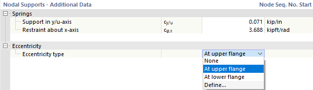
Enter the characteristic values of springs that are available for the lateral support or the rotation about the supported axes. You can also specify stiffnesses for warping springs.
The Eccentricity refers to the lateral support in y/u and, depending on the position of the compression flange, it can have a stabilizing or destabilizing effect for the lateral-torsional buckling. The list offers a support on an upper or a lower flange, as well as the option for defining it manually.
">stabilityImportTaby/u or kz/v should be applied.
">image021242@
About Axis
Specify the load cases of the stability analysis from which the effective lengths are to be imported. You can define a mode shape of a specific load case for each principal axis.
The mode shapes are properties of a load case or a load combination. First, select in the "Load Case / Load Combination" list the load situation that is governing for the buckling mode. The list only contains those load cases and load combinations with a specified stability analysis.
In the next step, define the governing "Mode No." The list of mode shapes is available for all calculated load cases and load combinations.
Click the
![]() button to display the mode shapes in the graphic window of the main program.
button to display the mode shapes in the graphic window of the main program.
Finally, select the "Member No." in the list. You can also use the
![]() button to define the member graphically in the work window.
button to define the member graphically in the work window.
Effective Length Factors
The table shows the effective length factors that were imported from the stability analysis for both principal axes. If you want to adjust the value manually, activate the "User-Defined" check box in the "About Axis" section. Thus, the text box becomes accessible.
The effective length factors displayed here are transferred to the Nodal Supports & Effective Lengths tab and can no longer be edited there. The "Absolute Values" option allows you to transfer the effective lengths Lcr,y/v and Lcr,z/v of the members from the stability analysis results. You can use this option, for example, if you want to apply the effective length to a member set from a member included therein.