


Local member cross-section reductions make it possible to consider weakening of the cross-section in the form of notches in the verifications.

Type and Position of the Reduction
Reductions can be defined for various locations along the member or member set. Specify the appropriate number of rows by selecting the corresponding notch types in the list:
- Start notch
- Internal notch
- End notch
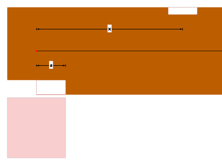
Then enter the location x on the member or member set for each one. This is the distance between the start node and the center of the reduction (see image Location x and length a of the notch). You can enter the distance as an absolute or relative value: Use the
![]() button to switch between the two input options.
button to switch between the two input options.
If the internal notches are at equal intervals and with equal notch lengths, check the 'Multiple' option. You can then define the number of notches and the spacing between the weakenings in the Parameters section.
The
![]() button allows you to sort the design parameters defined in the table in ascending order according to the x-location.
button allows you to sort the design parameters defined in the table in ascending order according to the x-location.
Parameters
In the lower section, define the geometry and position of the selected notch. For the multiple definition of an internal notch, enter the number and offset (uniform spacing) of the notches. Here too, you can enter the offset as an absolute or relative value.
If the member cross-section reduction is also a notch at a support, you can activate the Notch at support option (not for internal notches). This causes a reduced shear strength to be considered for the shear design at the reduced cross-section, depending on the geometry of the notch as a cross-section weakening.
The Consider notch for stability design check box makes it possible to account for the cross-section weakening when calculating the slenderness for the stability design. This is recommended, for example, for columns with member cross-section reductions in the middle third.
If the notch is fully or partially protected in case of fire, check the Set other data for fire protection design check box. You can then define a fire exposure that differs from the rest of the member by deactivating the check boxes for the protected sides.
Graphical Display
If you have assigned the member cross-section reduction to a member or member set, you can visually check the parameters. There are two ways to do this.
Dialog Graphic
The
![]() button in the dialog graphic allows you to display a model section in which the weakenings and supports of the objects are shown. To check the position of the notch or the start and end of the member, display the local member axis system.
button in the dialog graphic allows you to display a model section in which the weakenings and supports of the objects are shown. To check the position of the notch or the start and end of the member, display the local member axis system.

RFEM/RSTAB Work Window
In the Navigator - Display
![]() , you can activate the graphical display for Local Member Cross-Section Reductions including limit lines in the Model → Timber Design category. For all members and member sets with member cross-section reductions, the notches are displayed at the corresponding locations in the model.
, you can activate the graphical display for Local Member Cross-Section Reductions including limit lines in the Model → Timber Design category. For all members and member sets with member cross-section reductions, the notches are displayed at the corresponding locations in the model.
