


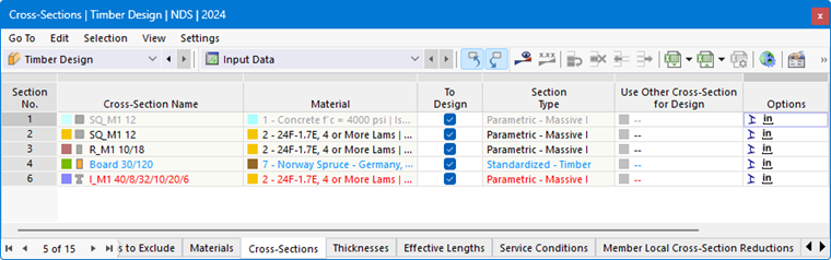
The Cross-Sections table in the “Timber Design” category lists all the cross-sections you have created in the model.
Allowable Cross-Sections
The timber design of member cross-sections is based on the standard. Whether a cross-section is allowable and relevant for the design can be determined by the text color. The colors mean:
- Black: The cross-section is suitable for the design and is used for the objects to design.
- Red: The cross-section is not suitable for the timber design.
- Blue: The cross-section is not used in the model.
- Gray: The cross-section is not used for the objects to design.
Depending on the standard, cross-sections of the Thick-walled I category, types
 and
and
 of the Standardized category, as well as
 of the Built-up category are allowable for timber design. Cross-sections from the cross-section properties program RSECTION can also be designed, provided that the calculation is performed using finite element analysis software.
Material of the Timber type should be assigned to all cross-sections.
The categories of the individual cross-sections are specified in the “Cross-Section Type” table column.
Objects with an invalid cross-section are not considered in the design—even if the “To Design” option is activated for that cross-section. They are automatically marked as “Not Valid / Deactivated” in the Objects to Design table.
Removing Cross-Section from Design
For a valid cross-section, you can exclude from design all objects to which the cross-section is assigned by deactivating the “To Design” check box. This classifies these objects as “Not Valid / Deactivated” in the Objects to Design table and excludes them from the design.
Adjusting Cross-Section
If necessary, you can adjust the cross-section properties in the editing dialog box. To do this, double-click the cross-section’s row or click the
 button in the table toolbar.
Icons for default values or modified values are displayed in the “Options” column of the table (see the image Table “Cross-Sections”). They allow for a quick overview of the cross-sections used. For example, the
 icon is assigned to a rotated cross-section.
Use Other Section for Design
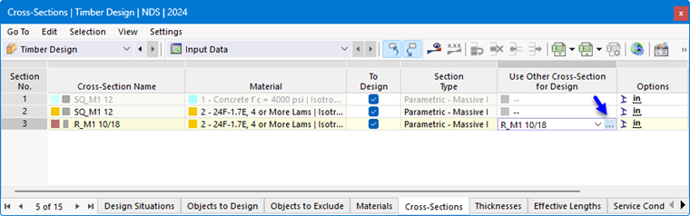
You can use other sections for design instead of the ones used for the RFEM/RSTAB calculation: To do this, click in the corresponding row of the “Use Other Section for Design” table column. You can then use the
 button to import a section from the library.
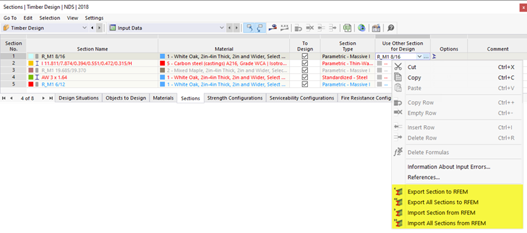
If there is a different cross-section stored in the column, additional options are available in the shortcut menu. You can use these to transfer the new cross-section to RFEM or RSTAB in order to use it in the structural analysis as well. It is also possible to re-import the original cross-section into the table.
Optimizing Cross-Section
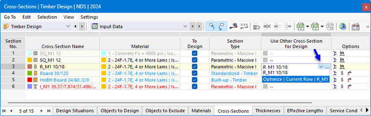
The Timber Design add-on provides the option of optimizing standard cross-sections. In this simplified optimization, the program searches for the smallest possible cross-section within the same cross-section series that fulfills all design checks with a design criterion less than the maximum allowable design ratio specified in the Global Settings dialog box.
To optimize a cross-section, click in the corresponding cell of the “Use Other Section for Design” table column. Then, select the “Optimize” option from the list.
The cross-section editing dialog box appears. In the “Optimization | Timber Design” tab, you can specify the parameters for the optimization.
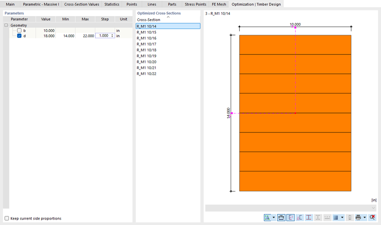
In the “Geometry” column, select the parameter(s) that you want to change. In the “Min” and “Max” columns, you can then enter the lower and upper limits for the parameter. The “Step” controls the interval over which the parameter’s dimensions vary during the optimization process. If you want to “Keep current side proportions”, select the corresponding check box and specify the parameters for optimizing the external dimensions.
The same conditions apply to cross-section optimization as when using a different cross-section (see above). The design checks are performed for all cross-section variants using the internal forces from the structural analysis. The optimal variant is then displayed in the table column. The effects of the modified cross-section on the stiffnesses and internal forces in the RFEM/RSTAB model are not taken into account. Therefore, use the options in the shortcut menu to transfer the optimized cross-sections to the model (see the image Shortcut Menu when Using Other Section).
Comprehensive structural optimization is possible using the Model Optimization add-on.