


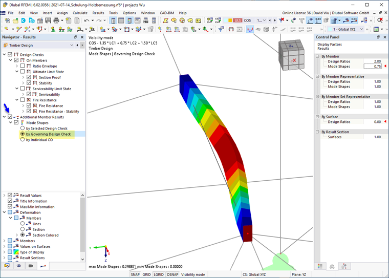
The navigator category Additional Member Results allows you to graphically display the mode shapes of members and member sets. The mode shapes are not displayed in the tables.
Mode Shapes
If the Ermittlungsart des idealen Verzweigungsmoments eigenvalue method is used to determine the elastic critical moment Mcr or the critical load factor αcrit for the lateral-torsional buckling design, the corresponding mode shape is also available graphically as a result.
The mode shapes can be displayed based on different criteria:
- According to selected design
The mode shape is displayed specifically for the design that is selected in the results table. In this case, the design always refers to a member or member set. The mode shape of this object is displayed in the work window for the load situation used in the specific design. This option is suitable for the targeted verification of a specific design.
- According to governing design
The mode shapes that are governing for the respective stability analysis are displayed for all objects. Thus, several mode shapes are shown next to each other in the graphic, although these can occur independently of each other or be based on different load situations. This option is particularly suitable in combination with Visibilities for the documentation of the results when the mode shapes of the visible objects are displayed.
- According to individual LC
The mode shapes that apply to a specific load combination are displayed for all objects – regardless of whether this LC is governing for the design. Set the load combination via the list of loads in the toolbar. This option is suitable for a plausibility check of the defined boundary conditions and nodal supports.
Scaling of Mode Shapes
In the lower navigator section, you can select how the dimensionless numerical values of the mode shapes are to be scaled to the reference length 1. This method is also referred to as "normalization".
- |u| = 1
The value of the mode shape vector is scaled to 1. The maximum total displacement |u| is considered here.
- max {uX; uY; uZ; φX; φY; φZ} = 1
This approach considers the entire eigenvector, including the rotational components. The maximum is searched for as a reference, and this component is then set to 1.
|
uj |
Translational component (j is the direction X/Y/Z) |
|
𝜑j |
Rotational component (j is the direction X/Y/Z) |