


The geometry of the model is defined by nodes. They are essential for creating lines, and thus members, surfaces, and solids. When entering members or surfaces graphically, the nodes are created automatically.

The node number is assigned automatically, but can be changed. The order is irrelevant for the numbering. It does not have to be continuous, either; gaps in the numbering are allowed.
Main
The Main tab manages the most important node parameters.
Node Type
Various node types are available for selection in the list.
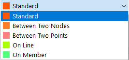
Standard
This type of node is used most frequently. Standard nodes can be placed graphically in the work plane or anywhere in the workspace by specifying coordinates. When entering lines or rotated surfaces graphically, standard nodes are created as well. Standard nodes are displayed in red in the model.
Between Two Nodes
The node lies on the connection line existing between two other nodes. Thus, it is not necessary to define a line and then to divide it by an intermediate node. The reference nodes and the distance must be defined in another tab.

Between Two Points
The node lies on the connection line existing between any two points. The points and the distance need to be defined in another tab (see the image Defining Node Between Two Nodes).
On Line
With this node type, a line is not divided into two lines, but remains complete. In this way you can, for example, place nodal loads on the line, or you can force FE nodes. The line and the distance need to be defined in another tab.
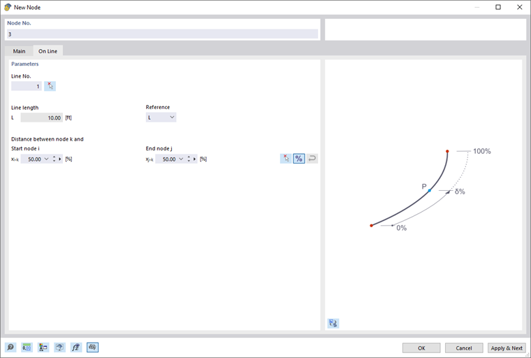
Use the
![]() button to switch between relative and absolute distances.
button to switch between relative and absolute distances.
On Member
With this node type, a member is not divided into two members, but remains complete. In this way it is possible, for example, to arrange singular lateral supports on the member. The member and the distance need to be defined in another tab (cf. the image Defining Node on Line).
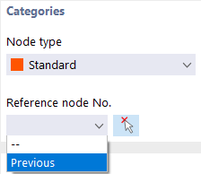
Reference Node
These coordinates usually refer to the origin of the global coordinate system (entry "--"). It is also possible to define the coordinates in relation to another node. This is useful, for example, to place the node at a distance from a defined position. For this, you can use the "Previous" option in the list. The reference node can also be entered directly or selected with
![]() on the model.
on the model.
Coordinate System
The coordinate system represents the reference system where the position of the node in space is described. In most cases, nodes can be defined in the "Global XYZ" coordinate system. However, user-defined coordinate systems are also possible. The chapter Coordinate Systems describes how to create a new coordinate system. All coordinate systems are right-hand oriented.
Coordinate Type
Depending on the model geometry, various formats are available for describing the nodal position.
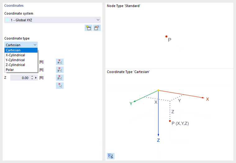
In most cases, nodes can be defined as "Cartesian": The X-, Y-, and Z-axes describe a translatory extension (distances), whereby all directions are equal. In contrast, cylindrical coordinate types facilitate the input of rotationally symmetric geometries. You have to specify the position of the node by means of the distance, radius, and angle. The polar coordinate type allows you to define a node in a spherical system by means of a radius and two angles.
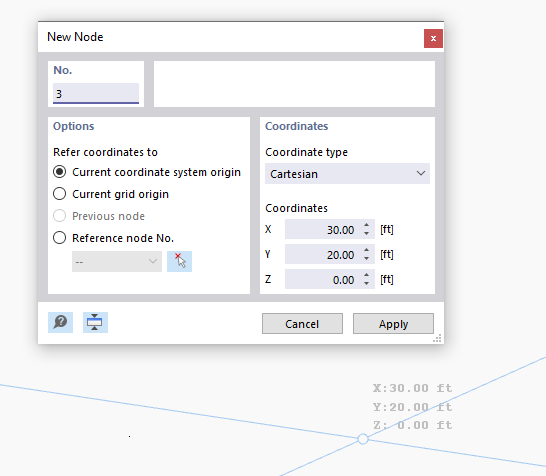
Coordinates
The position of the node can be described by its coordinates X, Y, Z. If the coordinate type is cylindrical or polar, you have to specify the distances and angles. In this case, the "Global coordinates" of the node are also displayed in the Cartesian coordinate system.
Use the Apply & Next button to define several nodes without leaving the dialog box.
Support
You can assign a support to the node. The degrees of freedom and spring constants have to be defined under the support conditions (see the chapter Nodal Supports).
Mesh Refinement
With a mesh refinement, you can influence the mesh size of the FE mesh in the area around the node (see the chapter Nodal Mesh Refinements). Thus, it is independent of the general mesh settings. In the "Mesh Refinement" tab, you can select a refinement or define a new one.
Nodal mesh refinements affect the generation of the FE mesh. Use the nodal mesh refinement to achieve an adjusted discretization in the refinement area around the node, as it may be necessary in corner areas or when connecting members to surfaces.
Release
A release at the node offers the option of decoupling the model at this point (see the chapter Nodal Releases). In this way, you can control which displacements or rotations are transferred on the node.
Link to Nearby Objects
A link automatically connects the node to another object that is located within a certain radius of the node (see the chapter Nodal Links). You can assign the link type in a new tab.
Setting Nodes Graphically
If you open the "New Node" dialog box with the
![]() button, you can set nodes directly with a click in the work plane.
button, you can set nodes directly with a click in the work plane.
Nodes are usually snapped to the grid points that are aligned with the current coordinate system. If you enter the coordinates manually in the dialog box, you can apply them with Apply. However, make sure to leave the pointer within the dialog box so that your entry is not overwritten by a new position.