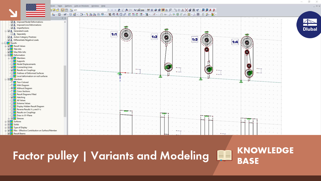
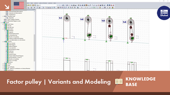
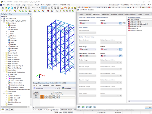
Modeling in RFEM
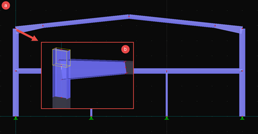
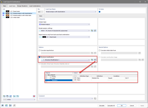
During the modeling, you have to enter the cable as a continuous polyline with at least three nodes. Thus, the program "knows" that the entire cable is an element. Then, you can assign the "Cable on Pulleys" member type to this polyline. At least one end of the cable member must have a fixed support or a member, so that the applied tensile load can be transferred. Since the tensile force should be constant in the "cable on pulley", no further definition is necessary for the connected elements. The adjacent elements or nodal supports receive deflection forces if there is buckling on the cables.
When modeling, rigid members were applied in such a way that the slab force can be displayed on a support. Additional stabilizing supports were arranged on the loose pulleys to counteract the instability.
The required pulling distance was applied by means of an imposed nodal deformation.
KB 001658 | Modeling of Factor Pulleys in RFEM
The design of cold-formed steel members according to the AISI S100-16 / CSA S136-16 is available in RFEM 6. Design can be accessed by selecting “AISC 360” or “CSA S16” as the standard in the Steel Design Add-on. “AISI S100” or “CSA S136” is then automatically selected for the cold-formed design.
RFEM applies the Direct Strength Method (DSM) to calculate the elastic buckling load of the member. The Direct Strength Method offers two types of solutions, numerical (Finite Strip Method) and analytical (Specification). The FSM signature curve and buckling shapes can be viewed under Sections.
In SHAPE-THIN 8, the effective cross-section of stiffened buckling panels can be calculated according to EN 1993-1-5, Cl. 4.5.
The critical buckling stress is calculated according to EN 1993-1-5, Annex A.1 for buckling panels with at least 3 longitudinal stiffeners, or according to EN 1993-1-5, Annex A.2 for buckling panels with one or two stiffeners in the compression zone. The design for torsional buckling safety is also performed.
- Craneway and weld stress analysis
- Craneways and weld fatigue design
- Deformation,
- Plate buckling analysis for wheel load introduction
- Stability analysis for lateral torsional buckling according to the second-order analysis of torsional buckling (1D FEA element)
For the design according to Eurocode 3, the following National Annexes are available:
- DIN EN 1993-6/NA:2010-12 (Germany)
- NBN EN 1993-6/ANB:2011-03 (Belgium)
- SFS EN 1993-6/NA:2010-03 (Finland)
- NF EN 1993-6/NA:2011-12 (France)
- UNI EN 1993-6/NA:2011-02 (Italy)
- LST EN 1993-6/NA:2010-12 (Lithuania)
- NEN EN 1993-6/NB:2012-05 (Netherlands)
- NS EN 1993-6/NA:2010-01 (Norway)
- SS EN 1993-6/NA:2011-04 (Sweden)
- CSN EN 1993-6/NA:2010-03 (Czech Republic)
- BS EN 1993-6/NA:2009-11 (United Kingdom)
- CYS EN 1993-6/NA:2009-03 (Cyprus)
In addition to the National Annexes listed above, you can also define a specific NA, applying user-defined limit values and parameters.
All results are arranged in result windows sorted by different topics. The design values are illustrated in the corresponding cross-section graphic. The design details cover all intermediate values.
General Stress Analysis
CRANEWAY performs the general stress analysis of a craneway girder by calculating the existing stresses and comparing them with the limit normal, limit shear, and limit equivalent stresses. Welds are also subjected to the general stress analysis with regard to parallel and vertical shear stresses and their superposition.
Fatigue Design
Fatigue design is performed for up to three cranes operating at the same time, based on the nominal stress concept according to EN 1993-1-9. In the case of fatigue design according to DIN 4132, a stress curve of crane passages is recorded for each stress point and evaluated according to the Rainflow method.
Buckling Analysis
Buckling analysis considers the local introduction of wheel loads according to the EN 1993-6 or DIN 18800-3 standards.
Deformation,
Deformation analysis is performed separately for the vertical and horizontal directions. The available related displacements are compared to the allowable values. You can specify the allowable deformation ratios individually in the calculation parameters.
Lateral-torsional buckling analysis
The lateral-torsional buckling analysis is performed in accordance with the second-order analysis for torsional buckling considering imperfections. The general stress analysis has to be fulfilled with the critical load factor greater than 1.00. As a result, CRANEWAY displays the corresponding critical load factor for all load combinations of the stress analysis.
Support forces
The program determines all support forces on the basis of the characteristic loads, including dynamic factors.