Loading of Neck Fillet Welds
The neck fillet welds of welded I-sections or the flank fillet welds of welded box girders are subjected to a shear force parallel to the weld axis when the beam is bent. The cause of this longitudinal shear force is that the welds prevent the flanges and the web from being displaced against each other. Only in this way can the cross-section act as a composite cross-section.
The resulting shear stress in the weld can be determined from the shear force distribution. The following formula is used for this:
|
τ∥,Vz |
Längsschubspannung in den Halsnähten aus Schubkraft |
|
Vz |
Querkraft |
|
Sy |
Statisches Moment des angeschlossenen Querschnittsteils |
|
Iy |
Flächenträgheitsmoment des Gesamtquerschnitts |
|
∑a |
Summe aller Schweißnahtdicken, die an das betrachtete Querschnittsteil anschließen |
In the case of box girder cross-sections, the flank fillet welds are additionally stressed by an acting torsional moment. Here, the shear stress in the welds is determined as follows:
|
τ∥,Mx |
Längsschubspannung in den Flankenkehlnähten aus Torsionsmoment |
|
Mx |
Torsionsmoment |
|
Am |
Kernfläche |
|
aw |
Nahtdicke einer Flankenkehlnaht |
Checking on Surface Model in RFEM
Another method is the design of the neck welds on a surface model in RFEM. By using line releases, the shear flow in the connection can be read efficiently and then used for the evaluation. As an alternative, you can evaluate the shear stress on the web.
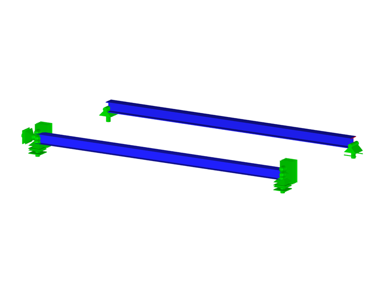
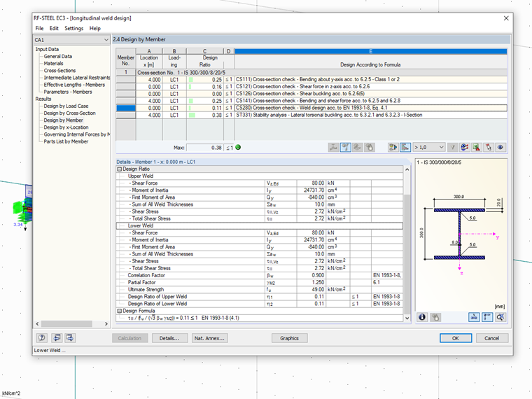
In the following example, the neck welds of the welded I‑beam are designed under bending. For this, the stresses determined on the surface model are compared to the results of the calculation in RF‑STEEL EC3.
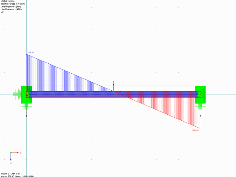
The neck seams are each selected with 5 mm; thus, a maximum longitudinal shear stress of τ∥ = 266 kN/m / (2 · 5 mm) = 2.66 kN/cm² results from the surface model.
An alternative evaluation results from the shear stresses τxy in the web. In this case, it is necessary to convert the stresses from the web thickness of 8 mm to the effective weld thickness of 10 mm. In the example, the distribution of the shear stress is evaluated over a section at the bottom weld.
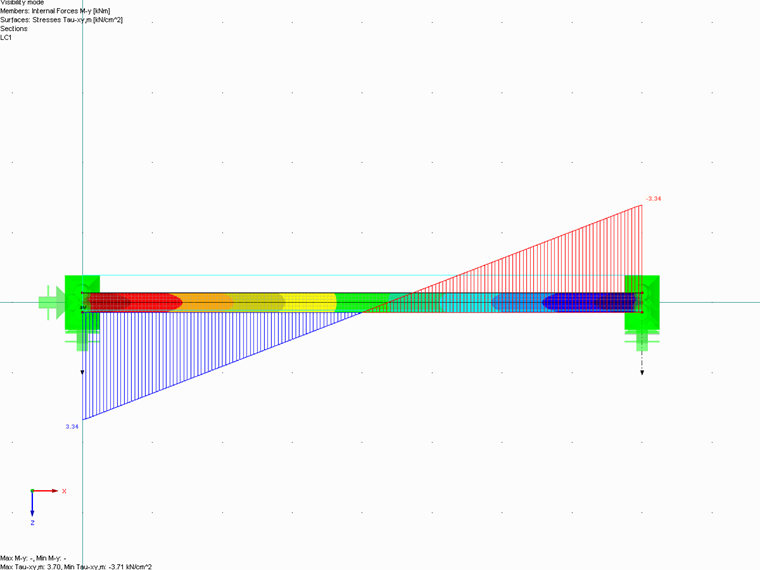
τ∥ = 3.34 kN/cm² · 8 mm/10 mm = 2.67 kN/cm²
The design in RF‑STEEL EC3 provides a comparable shear stress of τ∥ = 2.72 kN/cm².
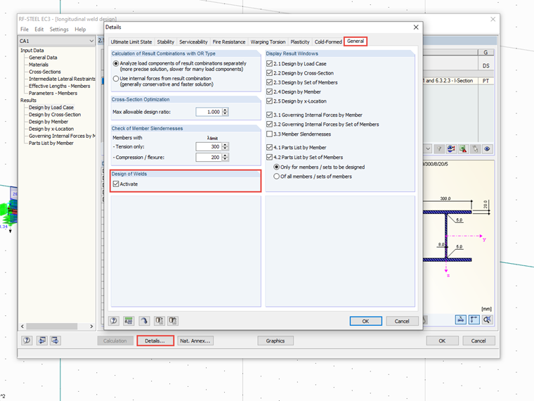
Please Note
Unfortunately, the design of the neck welds in the RF‑/STEEL EC3 add-on module is impossible for user-defined cross-sections created with SHAPE‑THIN.
The loading of the welds due to a concentrated load introduction (for example, wheel loads on crane runways) must be considered separately.