


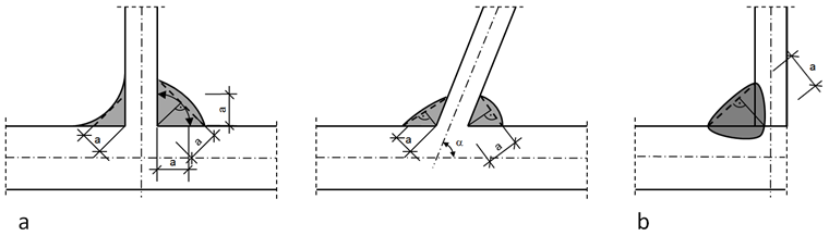
The effective weld thickness a of a fillet weld should be taken as the height of the largest triangle (with equal or unequal legs) that can be inscribed within the fusion faces and the weld surface, measured perpendicular to the outer side of this triangle; see Image 01.
Design Resistance of Fillet Welds
According to 1993‑1‑8 [1], the design resistance of a fillet weld is usually determined using the Directional Method or Simplified Method. The Directional Method is described below.
A uniform distribution of stress is assumed on the section of the weld, leading to the normal stresses and shear stresses shown in Image 02, as follows:
σ⊥ normal stress perpendicular to weld axis
σ|| normal stress parallel to weld axis
τ⊥ shear stress (in plane of fillet weld surface) perpendicular to weld axis
τ|| shear stress (in plane of fillet weld surface) parallel to weld axis
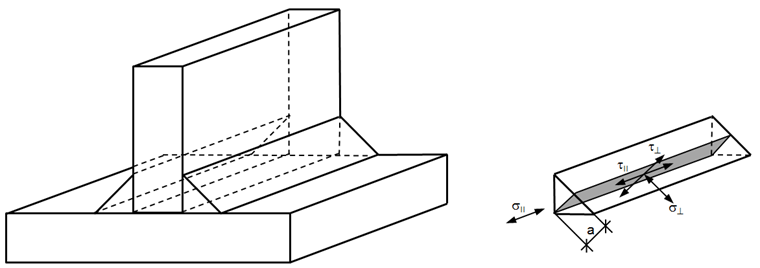
The normal stress σ|| parallel to the axis is not considered when verifying the design resistance of the fillet weld.
The design resistance of the fillet weld will be sufficient if the following conditions are met:
where
fu is the nominal ultimate tensile stress of the weaker part joined,
βw is the appropriate correlation factor (see EN 1993‑1‑8, Table 4.1)
γM2 is the partial safety factor for the resistance of welds.
Example
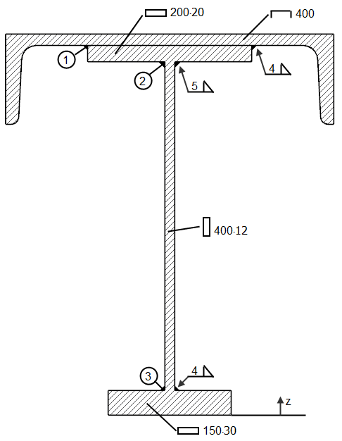
Design of a fillet weld of the beam displayed in Image 03 from [2].
Material: S235, fu = 36.0 kN/cm², βw = 0.8
Internal forces: Vz = 350 kN
Center of Gravity
Moment of Inertia
With regard to the centroid, the moment of inertia is:
Static Moments
With regard to the centroid, the static moments of the connected cross-sections are calculated using the welds ➀, ➁, and ➂:
Sy,1 = A1 ∙ (zS,1 - zS) = 91.48 ∙ (43.72- 30.88) = 1,175 cm³
Sy,2 = Sy,1 + A2 ∙ (zS,2 - zS)= 1175 + 40.00 ∙ (44.00 - 30.88) = 1,700 cm³
Sy,3 = A3 ∙ (zS - zS,3) = 45.00 ∙ (30.88- 1.50) = 1,322 cm³
Design of Welds
SHAPE-THIN
In SHAPE‑THIN, the shear stress (in the plane of the fillet weld surface) parallel to the weld axis τ|| can be calculated on fillet welds and the resistance can be designed. When modeling, the weld must be connected to the edges of two elements. One of these elements can also be a dummy element.
In Column H "Continuous Element" of Table 1.6 Welds, you can define the continuous elements. No weld stresses are calculated on these elements. If no element is specified in Column H, the weld stresses are determined on all elements to which the weld is connected. These elements can be taken from Column B, "Element No."
Image 04 shows the weld definition for the example described in this article.
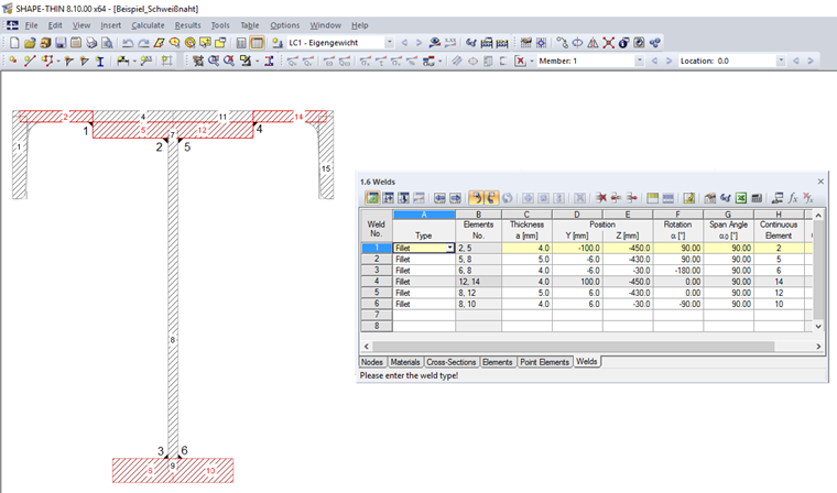
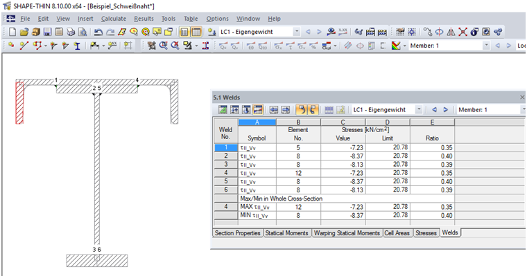
Table 5.1 Welds displays the resulting stresses τ|| for the welds defined in Table 1.6 Welds. Image 05 shows the weld stresses for the example described in this article.
Literature
[1] Eurocode 3: Design of Steel Structures - Part 1-8: Design of Joints; EN 1993‑1‑8:2005 + AC:2009
[2] Petersen, C. (1982). Stahlbau, (4th ed.). Wiesbaden: Springer Vieweg, 2013