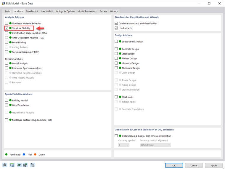
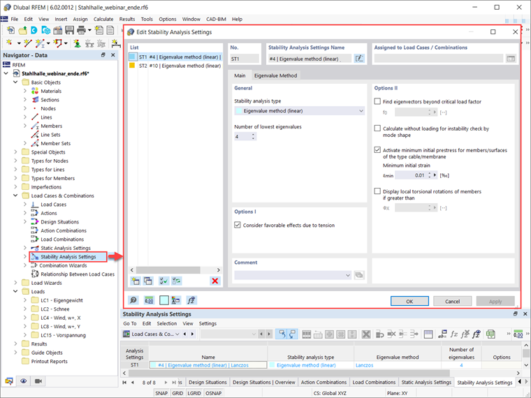
Assuming that the Structure Stability add-on is activated in Base Data (Image 2), you can define the stability analysis settings available in the Data navigator, as shown in Image 3. In this example, the Lanczos eigenvalue method is selected for the stability analysis and the number of lowest eigenvalues is set to 4. As Image 3 shows, you can consider other options in the stability analysis settings as well.
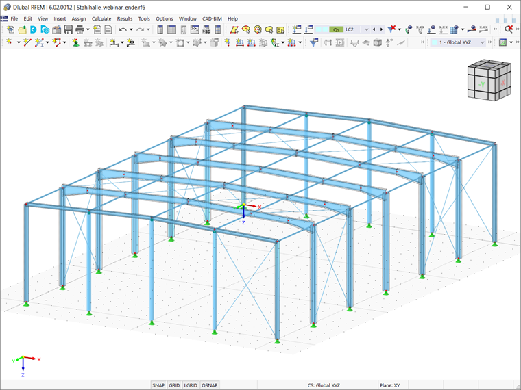
In RFEM 6, the stability analysis can be considered in terms of load cases, load combinations, and design situations. It is important to know that the program offers you the Combination Wizard (you can activate it in the Base tab of the Load Cases & Combinations window) to assist you in combining load cases into load combinations and design situations according to the preferred standard specification.
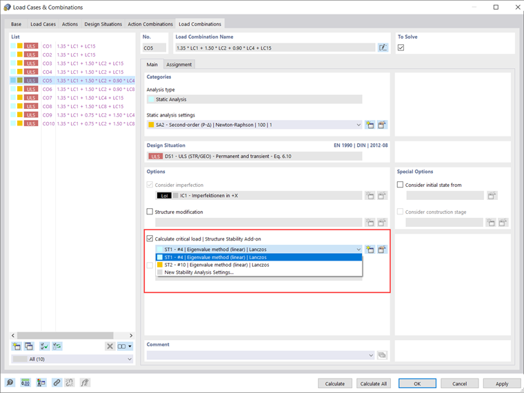
Hence, you can use this wizard to automatically create the load combinations listed in Image 4. In case of multiple load combinations such as in this example, you can select the one that you expect to govern (for example, CO5) and activate the “Calculate critical load | Structure Stability Add-on" option. At this point, you can choose the stability analysis settings that have already been defined, edit them, or create new ones.
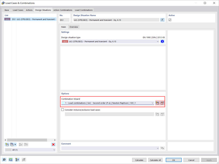
A more appropriate approach for carrying out the stability analysis that will be shown in this article is to consider not just one load combination, but all of them. This can be done easily if you activate the calculation of the critical load directly in the design situation.
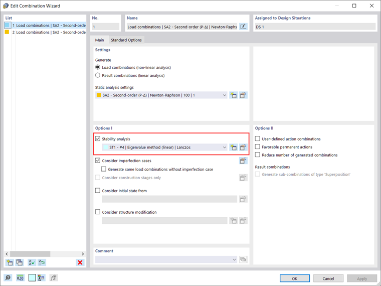
Assuming that the Combination Wizard has already been activated and it is available in the design situation of interest (Image 5), you can activate the “Stability analysis” option as shown in Image 6. This way, the stability analysis will be automatically activated for all the load combinations created with this combination wizard.
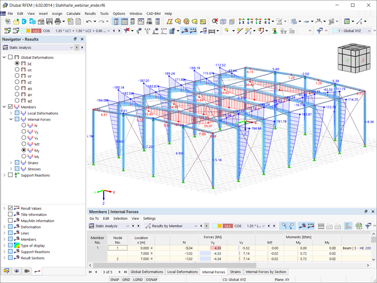
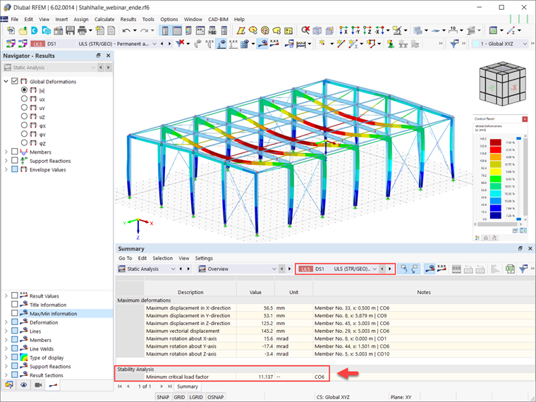
Once you calculate the design situation of interest, the results of all load combinations will be available in both graphical and tabular form. The most critical load factor of all the load combinations is automatically obtained for the selected design situation, and it is displayed in the summary of the Static Analysis table (Image 7).
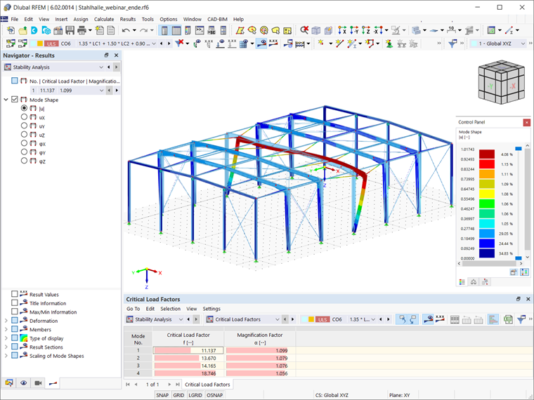
The governing load combination with which the critical load factor is associated is available as well, so that you can open the stability analysis results for this load combination and display the corresponding mode shape (Image 8). In this manner, you can see that the most critical stability issue for the load combinations present in the design situation of interest is in-plane flexural buckling.
At this point, it is important to consider that in the standard RFEM/RSTAB calculation, the 6 DOF solver is implemented and the obtained results are those discussed above (that is, in-plane flexural buckling being the most critical stability issue for the design situation of interest).
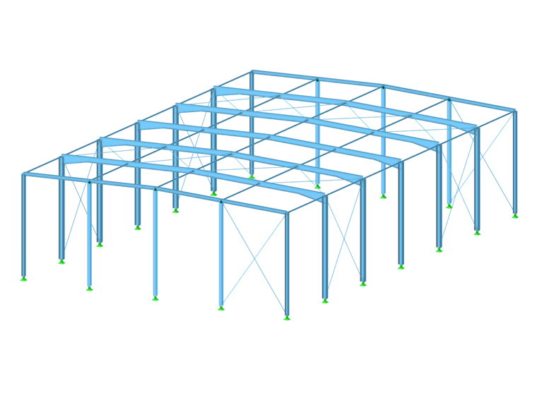
However, the results of the static analysis shown in Image 9 indicate that the applied loads result in bending moments My, so that a lateral torsion buckling problem of the main beam is expected as well. You can address this issue using the Torsion Warping (7 DOF) add-on, which allows you to consider cross-section warping as an additional degree of freedom when calculating members in RFEM and RSTAB. The way to do this will be discussed in an upcoming Knowledge Base article.