


Overview
The Chinese steel construction standard GB 50017 [1] describes the calculation method for designing the distortional buckling of a frame beam's bottom flange in Chapter 6.2.7. In contrast to the previous standard, this section represents a newly added design check.
The chapter is related to the stability calculation of the negative moment section of a frame beam. It provides the basis for verifying the stability of the beam's bottom flange or whether structural measures are to be taken.
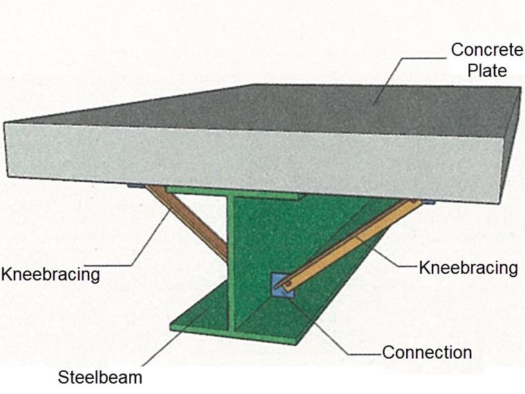
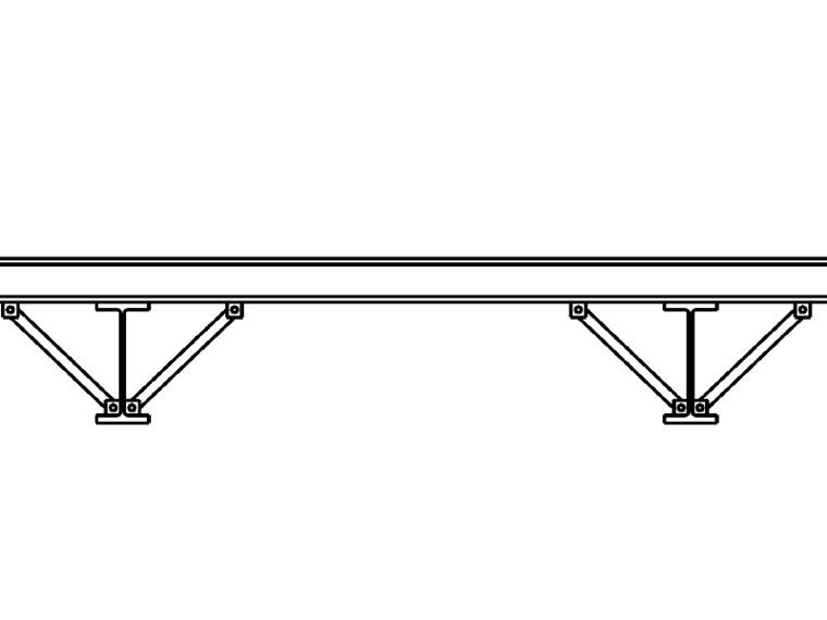
When a concrete slab is set upon the top flange, its effect is like a lateral support (composite construction), preventing problems of torsional buckling stability. If the distribution of the bending moment is negative, the bottom flange is subjected to compression and the top flange to tension.
While the top flange is restrained, the bottom flange can laterally deflect under the compressive load. If the lateral support provided by the stiffness of the web is insufficient, the angle between the bottom flange and the web intersection line is variable, so there is a possibility of distortional buckling of the bottom flange.
Analysis Method
Distortional Buckling
If the steel frame beams do not consider the restraint of the deformation by the upper concrete slabs, the members will deform and rotate freely. This means that the overall instability of the bending member occurs (lateral-torsional buckling, steel standard, Section 6.2.1).
Since the steel beam and the concrete slabs are two independent structural components, no compatibility of the deformation applies in this situation.
However, if the frame beam of the steel structure is laterally supported by the concrete slabs, its stability usually does not need to be analyzed: According to GB 50017, Section 6.2.1, the beam's lateral-torsional buckling does not need to be designed if the concrete slabs are firmly connected to the compression flange of the beam so that the lateral displacement of the beam's compression flange is prevented.
There are several ways in RFEM to model the composite effect of members and floor slabs, such as rib beams and surface model members. However, they represent integral structural components of concrete slabs in contrast to the explanations on frame beams above. Please find more detailed information on this subject in the corresponding articles in our Knowledge Base and in the Online Manuals.
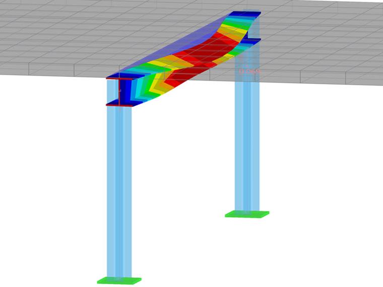
The image above shows the result of the FE calculation for the case when the top flange of the frame beam is supported. Thus, the bottom flange rotates about the center of the top flange. Therefore, according to [1] Section 6.2.7, the stability of the bottom flange must be verified.
Design Check Procedure According to EC 3
The design method according to EC 3 [2], Sections 6.3.2.4, 6.3.5.2, and BB.2 differs from the GB steel construction standard.
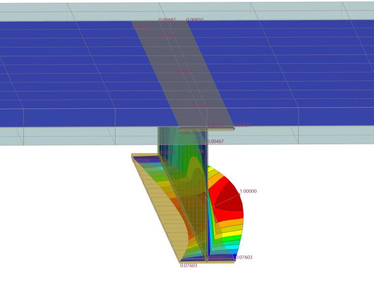
Structural components with laterally supported compression flanges may be considered as not prone to lateral-torsional buckling if specific conditions are met. For the design check regarding distortional buckling of a frame beam, the rotational stiffness and thus the torsional restraint of the bottom flange is checked first, as shown in the following image.
Design of Distortional Buckling of Bottom Flange According to GB 50017
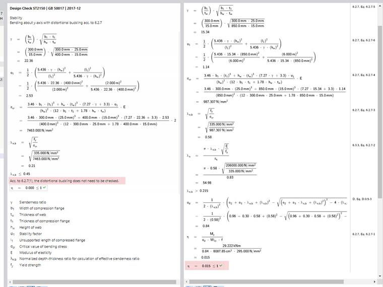
If the frame beam has a negative bending moment in the area near the support and a concrete slab is set upon the top flange, the stability calculation of the bottom beam flange must meet the following requirements according to Section 6.2.7 [1]:
- If λn,b ≤ 0.45, no design check is required for the bottom flange.
- If condition (1) is not met, the stability of the bottom flange must be calculated according to the following formula:
where
- b1 is the width of the compression flange (mm),
- t1 is the thickness of the compression flange (mm),
- W1x is the gross cross-sectional modulus around the strongest compressed fiber in the plane of the bending moment (mm³),
- ψd is the stability factor,
- λn,b is the standardized limiting slenderness,
- σcr is the critical stress for distortional buckling (N/mm²),
- l is the length between the laterally supported points (mm).
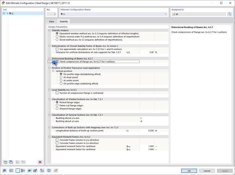
In RFEM, the corresponding function can be activated in the design configuration of the ultimate limit state setting.
The lateral support points can be specified under the effective lengths.
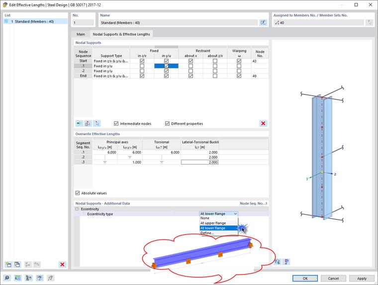
- After adding the intermediate nodes, the program automatically calculates the lateral support length in the negative moment zone of the frame beam. The other design lengths remain unchanged. The laterally supported distance is automatically taken into account.
- The specifications for load combinations and design situations remain unchanged.
- If the limiting slenderness is not exceeded, the design check result points out that the stability of the frame beam's bottom flange is not calculated. Otherwise, a detailed distortional buckling analysis is carried out to determine whether further laterally supported points are required.
- The laterally supported compression flanges still have to meet the requirements of the earthquake standard GB 50011, Chapter 8.3.3.
Conclusion
This article presented the calculation procedure for designing the distortional buckling of the bottom flange. The program checks whether the conditions of the torsional restraint are met by the lateral supports, or whether a further design check must be carried out in order to exclude distortional buckling. The design details are simple and understandable.