When using calculation methods with eigenvalue analysis (see Stability Analysis Type), you obtain the following results for each eigenvalue:
Critical Load Factor f (Eigenvalue)
… sets the actual load on the structure F in relation to the critical load Fcr, that is, to the critical buckling load that causes instability of the structure:
The factor provides notes about the stability of the structure and the need for a second-order analysis.
When using an incremental calculation method—that is, a nonlinear stability analysis; see Stability Analysis Type—the critical load factor corresponds to the load multiplier for which one of the following applies:
- The structural system cannot withstand any further load increase and becomes unstable; a convergent solution cannot be found.
- The maximum number of load increments or a criterion for stopping the load increase has been reached; see Tab: Increase Loading.
Magnification Factor α
… describes the relation between the moments according to the linear static and second-order analysis:
If f > 1 and the bending line is similar to the bending line of the undeformed structural system due to the load on the buckling mode, the magnification factor α is calculated as follows:
Deformation
… provides a graphical display of the mode shapes for (visual) evaluation of the stability behavior of the structure and for identifying critical elements. You can access the mode shapes in the Results navigator and in the tables.
In an incremental calculation, absolute deformations are displayed, similar to the structural analysis. To display individual load increments, activate the “Save results of all load increments” option (see Tab: Increase Loading).
Please also note the options for displaying results (especially on members) in the Results navigator.
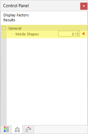
Image of adjusting the display of results: