


Answer:
The descriptions of the reinforcement in the Results navigator are defined as follows:
As,-z (top)
- Upper longitudinal reinforcement; that is, all longitudinal reinforcement that is above the centroidal axis of the cross-section (see Image 01)
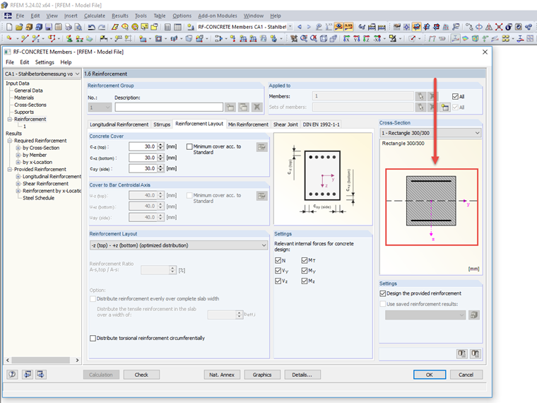
As,+z (bottom)
- Bottom longitudinal reinforcement; that is, all longitudinal reinforcement that is below the centroidal axis of the cross-section
As,T
- Total longitudinal reinforcement of the cross-section that is required due to torsion
As,-z (top) + As,T/2
- Upper longitudinal reinforcement (see above) plus one-half of the required longitudinal reinforcement from torsion
As,+z (bottom) + As,T/2
- Bottom longitudinal reinforcement (see above) plus one-half of the required longitudinal reinforcement from torsion
asw,T,stirrup
- Stirrup reinforcement from torsion
- Always single-leg, which means: reinforcement content from one leg on one stirrup member
- Resulting from the theoretical assumption of a spiral stirrup reinforcement
asw,V,stirrup
- Stirrup reinforcement from shear force
- Two-, three-, or four-leg, which means: reinforcement content from one leg on two, three, or four stirrup members
- Setting the number of legs under stirrup parameters, Window "1.6 Reinforcement", "Stirrups" tab; see Image 02
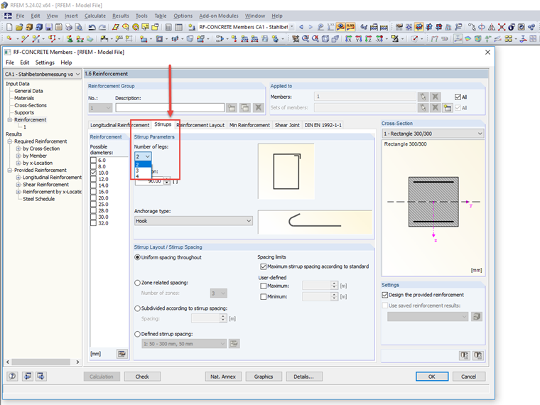
2*asw,T,stirrup + asw,V,stirrup
- Total stirrup reinforcement from torsion and shear force
- In this case, two-leg for torsion, therefore Factor 2 before asw,T,stirrup, shear reinforcement according to the setting from Image 02.