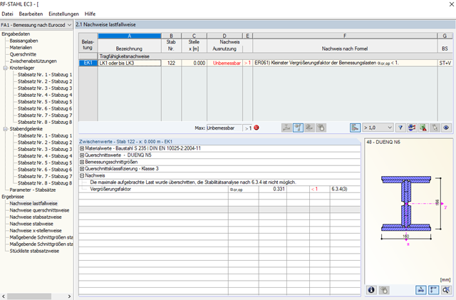
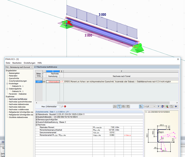
I design an asymmetric cross-section and get the message: "Non-designable: ER051) Moment about z‑axis on asymmetric cross-section, taper or set of members." Why?
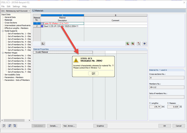
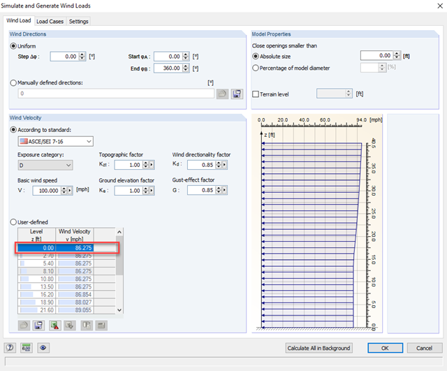
When calculating a cable using the STEEL EC3 add‑on module, there is the error message "Incorrect characteristic stresses for material No. 1! Please correct this in Table 1.2."
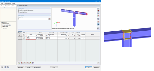
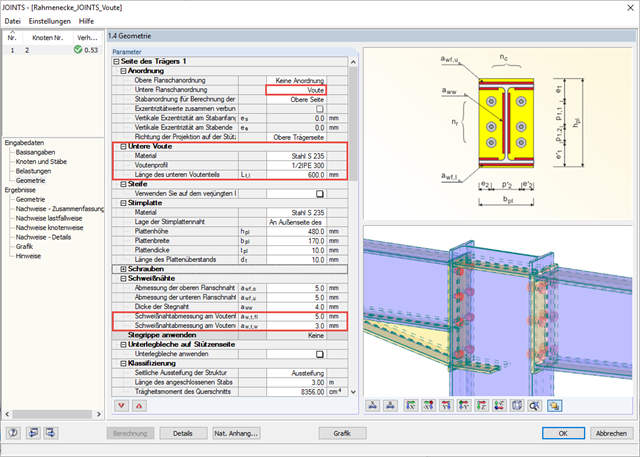
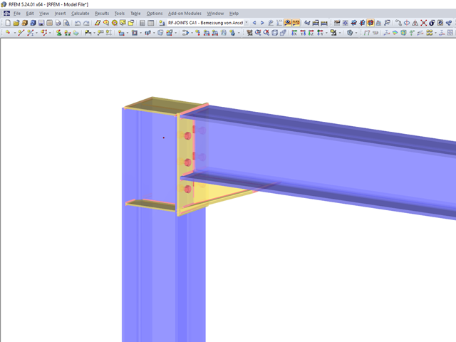
I would like to connect a column rigidly to a girder flange. However, in the RF‑/JOINTS Steel - Rigid add-on module, beams are always connected to a column flange. How can I create a continuous beam?
I am designing a set of members using the equivalent member method in RF‑/STEEL EC3, but the calculation fails. The system is unstable, delivering the message "Non-designable - ER055) Zero value of the critical moment on the segment".
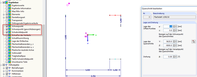
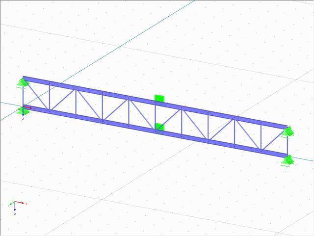
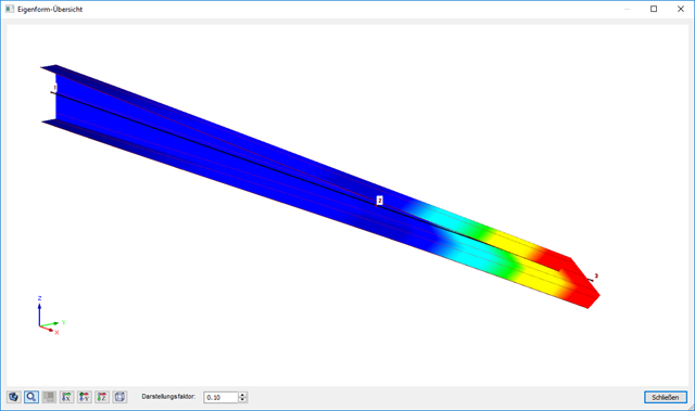
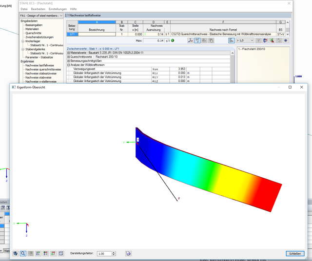
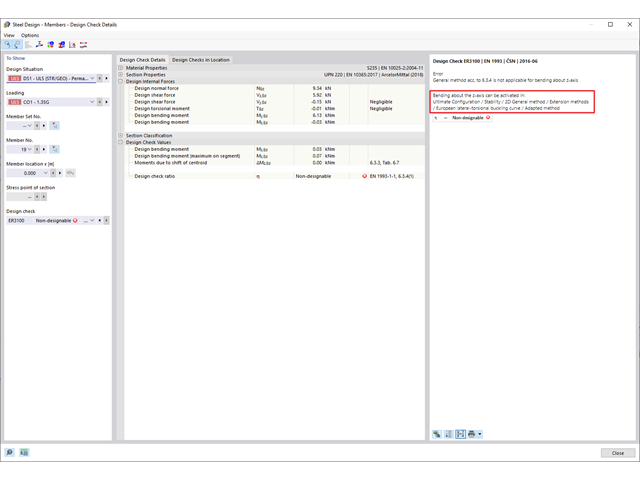
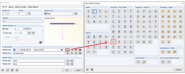
What are the options in RFEM 5 or RSTAB 8 for determining the ideal elastic critical moment for lateral-torsional buckling for any cross-sections and systems/loads? Is it also possible to design flat steel (brackets, flat steel stringers of staircases)?
When designing a beam, I would like to neglect the torsion included in the stability analyses using the filters described in Knowledge Base article #001498.
I define the filter, but the torsion warning appears at the same x‑location again. Do the design internal forces change, or why is that?
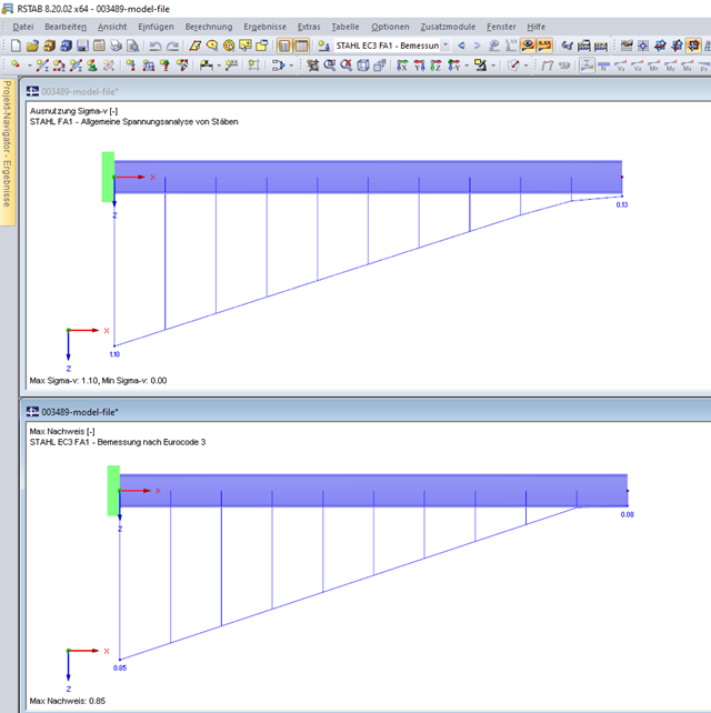
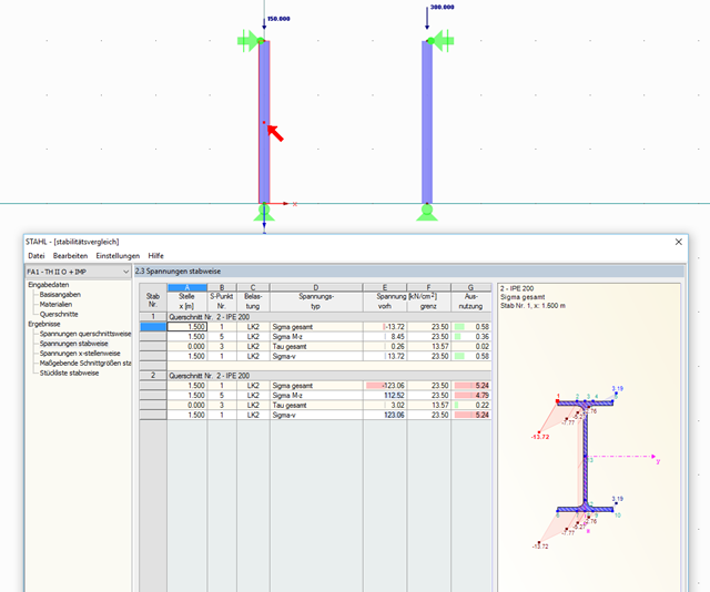
I am comparing the flexural buckling design according to the equivalent member method and the internal forces according to the linear static analysis with the stress calculation according to the second-order analysis, including imperfections. The differences are very large. What could be the reason for this?
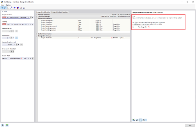
I am having trouble with the design of a steel structure. For a singly symmetric cross-section (UPE), the program cannot perform the stability analysis. It reports that the Equivalent Member Method 6.3.3 is not applicable for an unsymmetrical cross-section. Is it possible to design such cross-sections in the program?
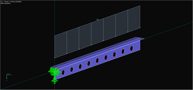
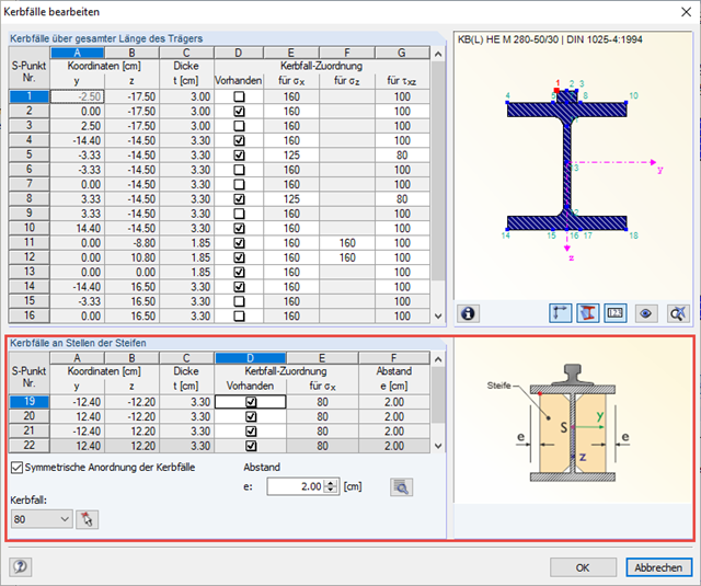
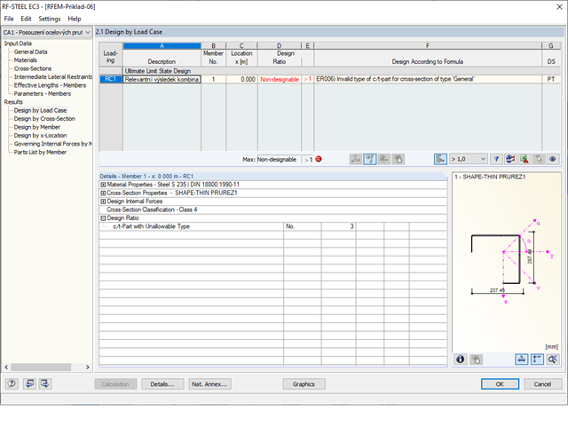
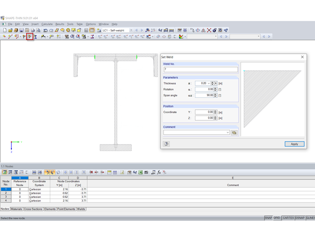
I am designing a cross-section created in the SHAPE‑THIN program using the design add-on module, but the program shows the error message "ER006 Invalid type of c/t-part for cross-section of type General". What can I do?
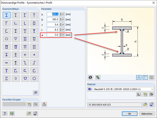
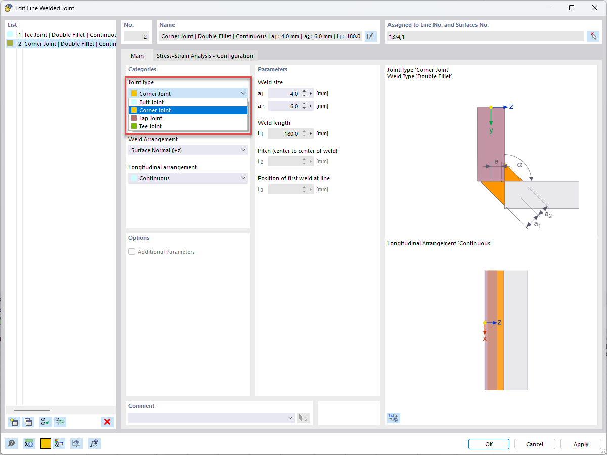
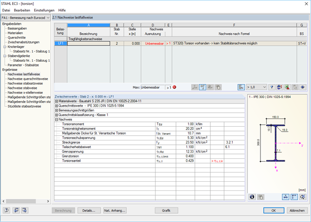
For the cross-section design of a flat steel, I obtain abnormally high shear stresses due to the torsion in the STEEL EC3 add-on module, which can be disproved by a simple manual calculation. What is the error?
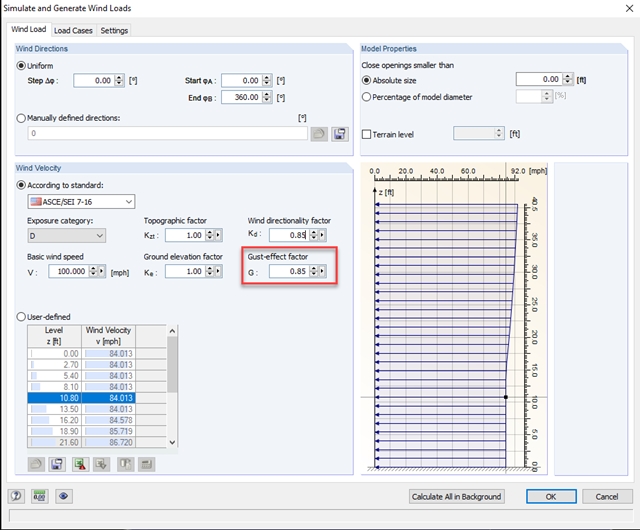
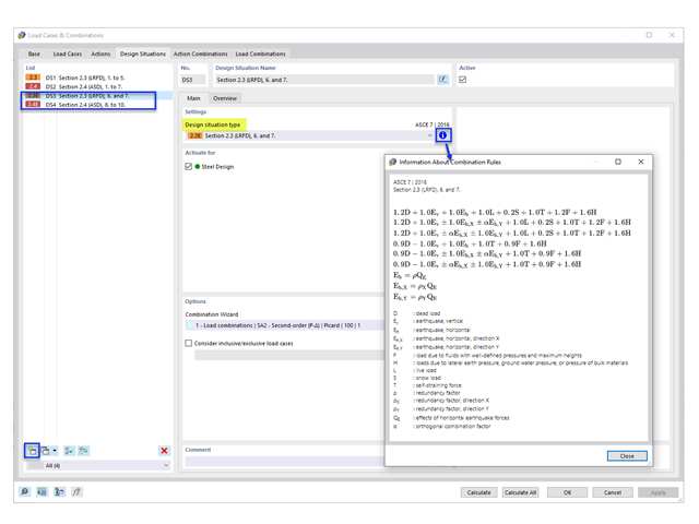
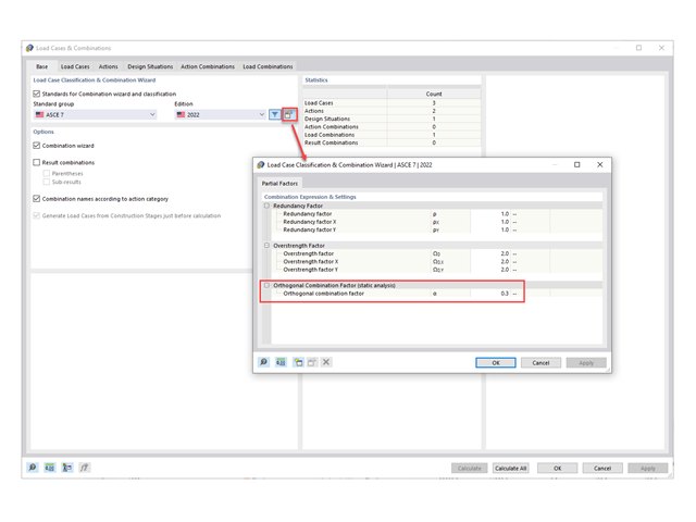
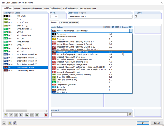
I would like to calculate a hall frame with loads from a crane runway. It is not quite clear to me what the various action categories denote. Can you explain it to me?
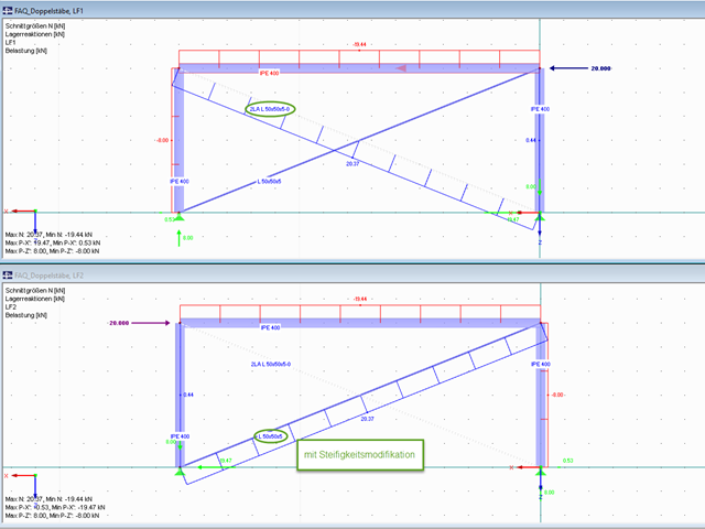
I used double members for the member input. Do I have to consider anything else, or is it better to enter a member with double cross-section properties?