37 Results
View Results:
Sort by:

The three types of moment frames (Ordinary, Intermediate, Special) are available in the Steel Design add-on of RFEM 6. The seismic design result according to AISC 341-22 is categorized into two sections: member requirements and connection requirements.

The Steel Design add-on in RFEM 6 now offers the ability to perform seismic design according to AISC 341-16 and AISC 341-22. Five types of seismic force-resisting systems (SFRS) are currently available.

The three types of moment frames (Ordinary, Intermediate, Special) are available in the Steel Design add-on of RFEM 6. The seismic design result according to AISC 341-16 is categorized into two sections: member requirements and connection requirements.

Moment frame design according to AISC 341-16 is now possible in the Steel Design add-on of RFEM 6. The seismic design result is categorized into two sections: member requirements and connection requirements. This article covers the required strength of the connection. An example comparison of the results between RFEM and the AISC Seismic Design Manual [2] is presented.

The design of an Ordinary Concentrically Braced Frame (OCBF) and a Special Concentrically Braced Frame (SCBF) can be carried out in the Steel Design add-on of RFEM 6. The seismic design result according to AISC 341-16 and 341-22 is categorized into two sections: Member Requirements and Connection Requirements.

Both the determination of natural vibrations and the response spectrum analysis are always performed on a linear system. If nonlinearities exist in the system, they are linearized and thus not taken into account. They are caused by, for example, tension members, nonlinear supports, or nonlinear hinges. This article shows how you can handle them in a dynamic analysis.

Compliance with building codes, such as Eurocode, is essential to ensure the safety, structural integrity, and sustainability of buildings and structures. Computational Fluid Dynamics (CFD) plays a vital role in this process by simulating fluid behavior, optimizing designs, and helping architects and engineers meet Eurocode requirements related to wind load analysis, natural ventilation, fire safety, and energy efficiency. By integrating CFD into the design process, professionals can create safer, more efficient, and compliant buildings that meet the highest standards of construction and design in Europe.

Windbreak structures are special types of fabric structures which protect the environment from harmful chemical particles, abate wind erosion, and help to maintain valuable sources. RFEM and RWIND are used for wind-structure analysis as one-way fluid-structure interaction (FSI).
This article demonstrates how to structural design windbreak structures using RFEM and RWIND.

The advantage of the RFEM 6 Steel Joints add-on is that you can analyze steel connections using an FE model for which the modeling runs fully automatically in the background. The input of the steel joint components that control the modeling can be done by defining the components manually, or by using the available templates in the library. The latter method is included in a previous Knowledge Base article titled “Defining Steel Joint Components Using the Library". The definition of parameters for the design of steel joints is the topic of the Knowledge Base article “Designing Steel Joints in RFEM 6".

Steel connections in RFEM 6 are defined as an assembly of components. In the new Steel Joints add-on, universally applicable basic components (plates, welds, auxiliary planes) are available for entering complex connection situations. The methods with which connections can be defined are considered in two previous Knowledge Base articles: “A Novel Approach to Designing Steel Joints in RFEM 6" and “Defining Steel Joint Components Using the Library".

- 000945
- Add-on Modules
- RF-FRAME-JOINT Pro 5
-
- JOINTS Steel | Column Base 8
- JOINTS Steel | DSTV 8
- JOINTS Steel | Pinned 8
- JOINTS Steel | Rigid 8
- JOINTS Steel | SIKLA 8
- JOINTS Steel | Tower 8
- JOINTS Timber | Steel to Timber 8
- JOINTS Timber | Timber to Timber 8
- RF-JOINTS Steel | SIKLA 5
- RF-JOINTS Steel | Column Base 5
- RF-JOINTS Steel | DSTV 5
- RF-JOINTS Steel | Pinned 5
- RF-JOINTS Steel | Rigid 5
- RF-JOINTS Steel | Tower 5
- RF-JOINTS Timber | Steel to Timber 5
- RF-JOINTS Timber | Timber to Timber 5
- FRAME-JOINT Pro 8
- Steel Structures
- Timber Structures
- Steel Connections
- Eurocode 3
- Eurocode 5
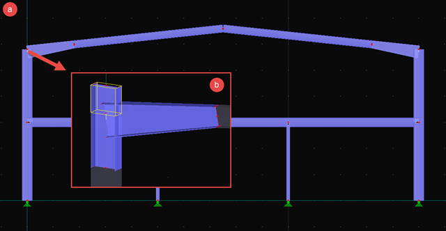
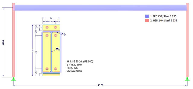
In addition to the result tables, you can create three-dimensional graphics in RF‑/FRAME‑JOINT Pro and RF‑/JOINTS. This is a realistic representation of a connection to scale.

RF-/DYNAM Pro - Equivalent Loads allows you to determine the loads due to equivalent seismic loads according to the multi‑modal response spectrum method. In the example shown here, this was done for a multi‑mass oscillator.

When connecting tension-loaded components with bolted connections, the cross-section reduction due to the bolt holes must be taken into account in the ultimate limit state design. This article describes how the design of the tension resistance according to DIN EN 1993‑1‑1 can be performed with the net cross-section area of the tension member in the RF‑/STEEL EC3 add-on module.

In the RF‑/HSS add‑on module, you can analyze the connections for nodes at which hollow sections join. RF‑/HSS performs the ultimate limit state designs according to EN 1993‑1‑8:2005.

Table 3.1 of EN 1993‑1‑8:2010‑12 defines the nominal values of the yield strength and the ultimate limit strength of bolts. The bolt classes given here are 4.6, 4.8, 5.6, 5.8, 6.8, 8.8, 10.9. The note for this table states that the National Annex may exclude certain bolt classes. For the NA of Germany, these are the bolt classes 4.8, 5.8, and 6.8.

According to Clause 6.2.2 (6) of EN 1993‑1‑8:2010‑12, you can apply friction using the friction coefficient to design the shear capacity.

This technical article deals with the design of structural components and cross-sections of a welded truss girder in the ultimate limit state. Furthermore, the deformation analysis in the serviceability limit state is described.

Closed circular cross-sections are ideal for welded truss structures. The architecture of such constructions is popular when designing transparent roofs. This article shows the special features of the connection design using hollow sections.

Designing rigid end plate connections is difficult for four-row connection geometries and multi-axis bending stresses, because there are no official design methods.

The elastic deformations of a structural component due to a load are based on Hooke's law, which describes a linear stress-strain relation. They are reversible: After the relief, the component returns to its original shape. However, plastic deformations lead to irreversible deformations. The plastic strains are usually considerably larger than the elastic deformations. For plastic stresses of ductile materials such as steel, yielding effects occur where the increase in deformation is accompanied by hardening. They lead to permanent deformations - and in extreme cases to the destruction of the structural component.

This technical article deals with the stability analysis of a roof purlin, which is connected without stiffeners by means of a bolt connection on the lower flange to have a minimum manufacturing effort.

This technical article analyzes the effects of the connection stiffness on the determination of internal forces, as well as the design of connections using the example of a two-story, double-spanned steel frame.

Both the determination of natural vibrations and the response spectrum analysis are always performed on a linear system. If nonlinearities exist in the system, they are linearized and thus not taken into account. Straight tension members are very often used in practice. This article will show how you can display them approximately correctly in a dynamic analysis.

A welded connection of an HEA cross-section under biaxial bending with axial force will be designed. The design of welds for the given internal forces according to the simplified method (DIN EN 1993-1-8, Clause 4.5.3.3) by means of SHAPE-THIN will be performed.

A site joint consisting of hollow sections with end plates will be designed. It is the bottom chord of a truss that has to be divided for transport reasons.

DIN EN 1998-1 with the National Annex DIN EN 1998-1/NA specifies how to determine seismic loads. The standard applies to structural engineering in seismic areas.

- 001555
- Modeling | Loading
- RFEM 5
-
- RSTAB 8
- RF-TIMBER AWC 5
- TIMBER AWC 8
- RF-TIMBER CSA 5
- TIMBER CSA 8
- RF-TIMBER Pro 5
- TIMBER Pro 8
- RF-JOINTS Timber | Timber to Timber 5
- JOINTS Timber | Timber to Timber 8
- RF-JOINTS Timber | Steel to Timber 5
- JOINTS Timber | Steel to Timber 8
- RF-LIMITS 5
- LIMITS 8
- RF-LAMINATE 5
- Timber Structures
- Laminate and Sandwich Structures
- Structural Analysis & Design
- Finite Element Analysis
- Steel Connections
- Eurocode 0
- Eurocode 5
- ANSI/AISC 360
- SIA 260
- SIA 265
In addition to determining loads, some particularities concerning the load combinatorics in timber design have to be considered. Contrary to steel structures, where the largest loading results from all unfavorable actions, in timber construction, the strength values depend on the load duration and timber humidity. Special characteristics have to be considered as well for the serviceability limit state design. The following article discusses the effects on the design of wooden elements and how this is possible with RSTAB and RFEM.
- 001545
- Modeling | Structure
- RFEM 5
-
- RF-FRAME-JOINT Pro 5
- RF-JOINTS Timber | Timber to Timber 5
- RF-JOINTS Timber | Steel to Timber 5
- RF-JOINTS Steel | Rigid 5
- RF-JOINTS Steel | DSTV 5
- RF-JOINTS Steel | Pinned 5
- RF-JOINTS Steel | Tower 5
- RF-JOINTS Steel | SIKLA 5
- RF-JOINTS Steel | Column Base 5
- Steel Structures
- Mechanical Engineering
- Cranes and Craneways
- Towers and Masts
- Process Manufacturing Plants
- Steel Connections
- Finite Element Analysis
- Structural Analysis & Design
- Eurocode 3
- DIN 18800
With RF-/FRAME-JOINT Pro, you can design frame joints according to DIN 18800 or Eurocode 3. When dealing with non-standardized joints or when a deeper insight into the connection and its behavior is required, modeling as a surface model is ideal. This article will show, in principle, how this kind of model is created.
This article deals with the stiffness of standardized joints according to the DSTV (German Steel Construction Association)/DASt (German Committee for Structural Steelwork) standards, often used in steel construction, and its effects on structural analysis and design results according to DIN EN 1993-1-1.

Fin plate connections are a popular form of pinned steel connection and are commonly used for secondary beams in steel structures. They can be used easily in beam structures arranged on the top edge (for example, working platforms). Manufacturing expenditures in the workshop as well as the onsite assembly costs are normally manageable. The design seems to be completed easily and quickly, but it has to be put into perspective to a certain extent in the following text. Moreover, this connection type is basically possible as a pinned beam-to-beam or pinned beam-to-column connection; the former case is the more common one in design practice.